Oil stain cleaning equipment with waste oil recovery function

A technology for cleaning equipment and oil recovery, which is applied in the direction of cleaning methods using liquids, cleaning methods using tools, cleaning methods and utensils, etc., which can solve problems such as inability to clean oil stains and decline in the cleaning effect of range hood oil stains, so as to avoid shedding Effect

Inactive Publication Date: 2021-01-22
广州度格网络科技有限公司
View PDF6 Cites 0 Cited by
  • Summary
  • Abstract
  • Description
  • Claims
  • Application Information

AI Technical Summary

Problems solved by technology

[0003] Because the brush on the waste oil recovery type automatic cleaning brush is straight, so that when the high-speed rotating brush cleans the grate partition of the pumping unit with oil stains on the inside, the straight brush head cannot clean the fence. Clean up the oil on the inner surface of the grid partition, resulting in a decline in the oil cleaning effect of the waste oil recovery automatic cleaning brush on the range hood

Method used


Image

  • Oil stain cleaning equipment with waste oil recovery function
  • Oil stain cleaning equipment with waste oil recovery function
  • Oil stain cleaning equipment with waste oil recovery function

Examples


Embodiment 1

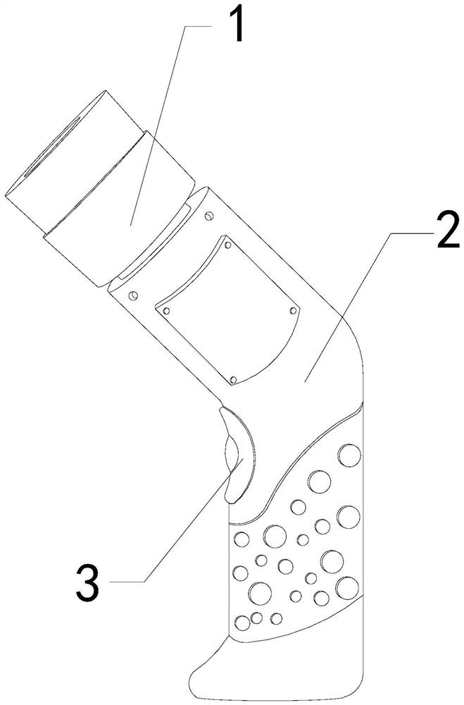
[0026] For example figure 1 -example Figure 5 Shown:

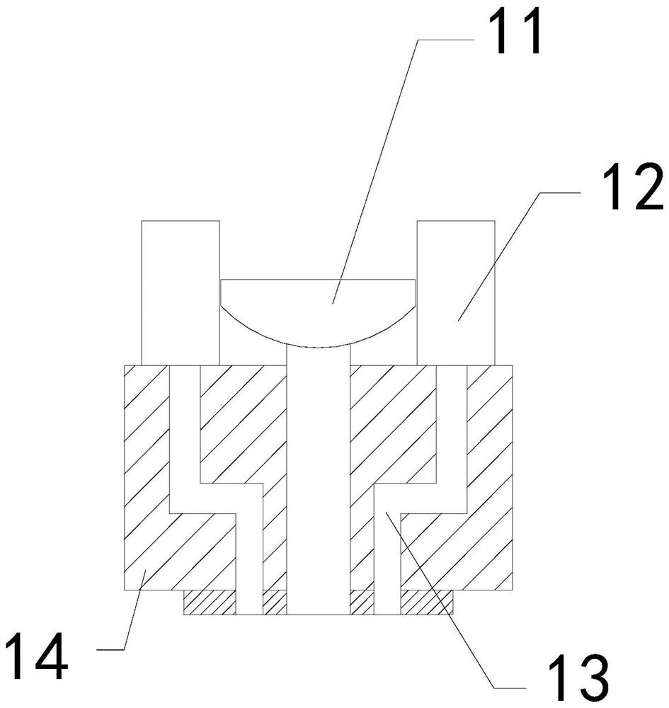
[0027] The present invention provides an oil cleaning device with the function of recycling waste oil. The upper end of 2 is movably engaged; the brush head 1 includes an oil guide plate 11, a brush 12, a liquid guide cavity 13, and a plate body 14. The oil guide plate 11 is embedded in the inner center of the plate body 14, and the hair The brush 12 is installed at the upper end of the plate body 14 , and the liquid-inducing cavity 13 and the plate body 14 are integrated structures.

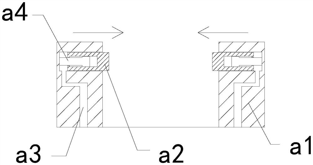
[0028] The brush 12 includes a board surface a1, an overhanging block a2, a through cavity a3, and a fixing rod a4. The overhanging block a2 is movably engaged with the fixing rod a4, and the through cavity a3 runs through the board surface. At the inner position of a1, the fixing rod a4 and the board surface a1 are an integrated structure, and there are two overhanging blocks a2, which are evenly distributed on the left and right sides ...

Embodiment 2

[0034] For example Image 6 -example Figure 8 Shown:

[0035] The movable plate b2 includes a lifting plate b21, a middle connecting rod b22, an elastic sheet b23, and a plate b24. The lifting plate b21 is embedded in the upper end position of the middle connecting rod b22, and the middle connecting rod b22 and the plate b24 are movable. The elastic piece b23 is installed between the middle connecting rod b22 and the plate b24. The reverse thrust generated by the cleaning liquid on the lifting plate b21 when the plate b24 slides down and resets can make the lifting plate b21 cooperate with the middle connecting rod b22. It slides upwards along the plate b24, so that the lifting plate b21 will not immediately bring down the oil stains.

[0036] Wherein, the lifting plate b21 includes an extrusion port c1, an upper plate c2, a bottom plate c3, and a liquid pipe c4. The extrusion port c1 and the upper plate c2 are an integrated structure, and the upper plate c2 is embedded in ...


PUM


Abstract

The invention discloses an oil stain cleaning equipment with a waste oil recovery function. The oil stain cleaning equipment structurally comprises a brush head, a machine body and a control button, wherein the control button is installed on the left side of the machine body, and the brush head is movably clamped with the upper end of the machine body. Cleaning liquid continuously extruded from the interior of the machine body enters a through cavity from a liquid guide cavity, therefore, the cleaning liquid inside the through cavity can push an outwards-extending block to extend outwards along a fixing rod, so that a cleaning brush on the outwards-extending block can be attached to the inner side of a barrier partition plate to rotationally clean the barrier partition plate, the cleaningliquid can be upwards extruded into a bottom plate through a liquid passing pipe, an outer attaching plate can be contracted inwards by extruding the outer attaching plate through the cleaning liquid,so that the cleaning liquid can be extruded upwards, oil stains adhering to the upper surface of a movable plate can be flushed away from bottom to top, and the situation that the oil stains adheringto the upper surface of the movable plate are difficult to fall off from the movable plate is effectively avoided.

Description

technical field [0001] The invention relates to the field of oil pollution cleaning equipment, in particular to an oil pollution cleaning device with the function of recycling waste oil. Background technique [0002] The waste oil recovery type automatic cleaning brush is mainly used for cleaning the oil stains in the kitchen. It can clean the oil stained areas inside the kitchen through the cooperation of the high-speed rotating cleaning brush head and the evenly extruded cleaning agent, and can clean the oil stains in the kitchen. The oil under the oil is sucked into the waste oil recovery type automatic cleaning brush through the middle oil suction device for collection, so as to facilitate subsequent centralized processing. Based on the above description, the inventor found that the existing oil cleaning equipment with waste oil recovery function There are mainly the following shortcomings, such as: [0003] Since the brush on the waste oil recovery type automatic clean...

Claims


Application Information

Patent Timeline
Patent Type & Authority Applications(China)
IPC IPC(8): B08B1/04B08B1/00B08B3/02B08B13/00
CPCB08B1/002B08B1/04B08B3/02B08B13/00
Inventor 苏培湘
Owner 广州度格网络科技有限公司
Why Eureka
Try Eureka