Self-lifting construction elevator cage
A construction elevator and self-lifting technology, which is applied to elevators, transportation and packaging in buildings, can solve problems such as incompatibility with different buildings, and achieve the effect of ensuring movement synchronization, smooth lifting and rotation, and rotation synchronization.
- Summary
- Abstract
- Description
- Claims
- Application Information
AI Technical Summary
Problems solved by technology
Method used
Image
Examples
Embodiment 1
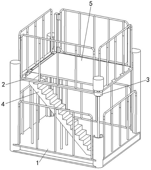
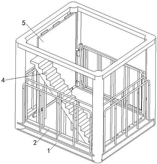
[0027] A kind of self-lifting construction elevator ladder cage of the present embodiment, as figure 1 and figure 2 As shown, the first ladder cage 1 including the top opening and the second ladder cage 2 vertically slidably arranged inside the first ladder cage 1 are arranged between the first ladder cage 1 and the second ladder cage 2 to drive the second ladder cage. The lifting device 3 for the lifting of the second ladder cage 2; the inside of the first ladder cage 1 is also provided with a staircase 4, and the bottom of the second ladder cage 2 is rotated to be provided with a turning base plate 5, which corresponds to the first ladder on the turning base plate 5. The stairway 4 inside the cage 1 is provided with an escape groove.
[0028] The first ladder cage 1 is a square frame structure, the top of the first ladder cage 1 is open, and the inside of the first ladder cage 1 is slidingly provided with a second ladder cage 2 along the vertical direction, and the inner b...
Embodiment 2
[0033] This embodiment is further optimized on the basis of embodiment 1, as shown in Fig. figure 1 , figure 2 , Figure 6 As shown, the first ladder cage 1 includes four uprights vertically arranged at the four corners of the rectangular area, the uprights are provided with chute 001 along the vertical direction, and the bottom plate of the second ladder cage 2 The four corners are respectively provided with slide blocks 002 corresponding to the slide grooves 001 on the four uprights, and the slide blocks 002 are slidably connected with the slide grooves 001.
[0034] The slider 002 is connected to the lifting end of the lifting device 3, and the lifting end of the lifting device 3 drives the slider 002 to slide vertically along the chute 001 on the column, thereby realizing the lifting of the second cage 2.
[0035] Other parts of this embodiment are the same as those of Embodiment 1, so details are not repeated here.
Embodiment 3
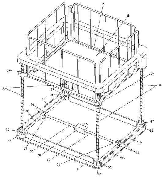
[0037] This embodiment is further optimized on the basis of above-mentioned embodiment 1 or 2, such as Figure 1-Figure 3As shown, the lifting device 3 includes a two-way reducer 31, a drive shaft 32, a driving helical gear 33, a driven helical gear 34, a driven shaft 35, a driving helical gear 36, a screw helical gear 37, a lifting screw 38, a nut seat 39. The two-way reducer 31 is installed on the inner bottom of the first ladder cage 1, and the output ends on both sides of the two-way reducer 31 are symmetrically connected to the drive shaft 32, and the output end of the drive shaft 32 is sleeved with a drive helical gear 33 Two driven shafts 35 are symmetrically arranged on the output end of the driving shaft 32 along the direction perpendicular to the driving shaft 32, and the input end of the driven shaft 35 is sleeved with a driven helical gear 34 meshed with the driving helical gear 33, the The output end of the driven shaft 35 is covered with a transmission helical ge...
PUM
 Abstract
Description
Claims
Application Information
 - R&D
- Intellectual Property
- Life Sciences
- Materials
- Tech Scout
- Unparalleled Data Quality
- Higher Quality Content
- 60% Fewer Hallucinations
Browse by: Latest US Patents, China's latest patents, Technical Efficacy Thesaurus, Application Domain, Technology Topic, Popular Technical Reports.
© 2025 PatSnap. All rights reserved.Legal|Privacy policy|Modern Slavery Act Transparency Statement|Sitemap|About US| Contact US: help@patsnap.com


