A self-lifting construction elevator cage

A construction elevator and self-elevating technology, which is applied to elevators in buildings, transportation and packaging, etc., can solve problems such as incompatibility with different buildings, and achieve the effect of ensuring rotation synchronization, convenient switching, and smooth lifting

Active Publication Date: 2022-07-29
THE THIRD CONSTR & ENG OF CCFED +1
View PDF7 Cites 0 Cited by
  • Summary
  • Abstract
  • Description
  • Claims
  • Application Information

AI Technical Summary

Problems solved by technology

However, in the actual construction process, it is often necessary to work on buildings with different storey heights, and the traditional ladder cage with a fixed storey height cannot be compatible with the storey heights of different buildings.

Method used


Image

  • A self-lifting construction elevator cage
  • A self-lifting construction elevator cage
  • A self-lifting construction elevator cage

Examples


Embodiment 1

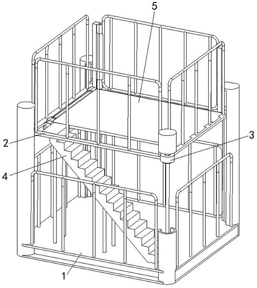
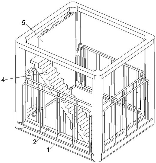
[0027] A self-elevating construction elevator ladder cage of the present embodiment, such as figure 1 and figure 2 As shown in the figure, a first ladder cage 1 with an opening at the top and a second ladder cage 2 vertically slidably arranged inside the first ladder cage 1 are provided between the first ladder cage 1 and the second ladder cage 2. The lifting device 3 for lifting the second ladder cage 2; the first ladder cage 1 is also provided with a staircase 4, and the bottom of the second ladder cage 2 is rotatably provided with a flipping bottom plate 5, and the flipping bottom plate 5 corresponds to the first ladder. The stairs 4 inside the cage 1 are provided with avoidance grooves.

[0028] The first ladder cage 1 is a box-shaped structure, the top of the first ladder cage 1 is open, the interior of the first ladder cage 1 is slidably disposed in the vertical direction with a second ladder cage 2 , and the inner bottom of the first ladder cage 1 is connected to the ...

Embodiment 2

[0033] This embodiment is further optimized on the basis of Embodiment 1, as shown in the figure figure 1 , figure 2 , Image 6 As shown in the figure, the first ladder cage 1 includes four uprights arranged at the four corners of the rectangular area in the vertical direction, the uprights are provided with chute 001 in the vertical direction, and the bottom plate of the second ladder cage 2 The four corners are respectively provided with sliders 002 corresponding to the chute 001 on the four uprights, and the slider 002 is slidably connected with the chute 001 .

[0034] The sliding block 002 is connected to the lifting end of the lifting device 3 , and the lifting end of the lifting device 3 drives the sliding block 002 to slide vertically along the chute 001 on the column, thereby realizing the lifting and lowering of the second ladder cage 2 .

[0035] The other parts of this embodiment are the same as those of Embodiment 1, and thus are not repeated here.

Embodiment 3

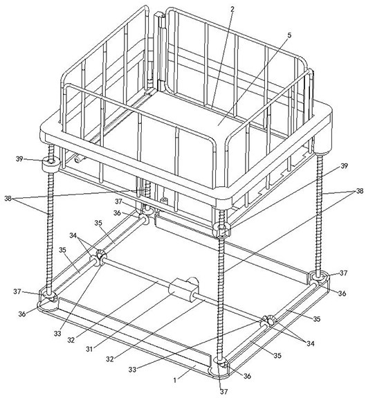
[0037] This embodiment is further optimized on the basis of the above-mentioned Embodiment 1 or 2, such as Figure 1-Figure 3As shown, the lifting device 3 includes a bidirectional reducer 31, a driving shaft 32, a driving helical gear 33, a driven helical gear 34, a driven shaft 35, a driving helical gear 36, a screw helical gear 37, a lifting screw 38, and a nut seat 39. The two-way reducer 31 is installed on the inner bottom of the first ladder cage 1. The output ends on both sides of the two-way reducer 31 are symmetrically connected with a drive shaft 32, and the output end of the drive shaft 32 is sleeved with a drive helical gear 33. ; Two driven shafts 35 are symmetrically arranged at the output end of the drive shaft 32 along the direction perpendicular to the drive shaft 32, and the input end of the driven shaft 35 is sleeved with a driven helical gear 34 meshing with the drive helical gear 33, the described The output end of the driven shaft 35 is sheathed with a tr...


PUM


Abstract

The invention discloses a self-lifting construction elevator ladder cage, comprising a first ladder cage with an open top and a second ladder cage vertically slidably arranged inside the first ladder cage, the first ladder cage and the second ladder cage There is a lifting device driving the second ladder cage to lift and lower; the first ladder cage is also provided with stairs, and the bottom of the second ladder cage is rotated and provided with a flipping bottom plate, and the flipping bottom plate corresponds to the first ladder cage. The internal stairs are provided with avoidance grooves; the present invention has the advantages of lifting and lowering the second ladder cage from the inside to the outside of the first ladder cage according to actual use requirements, thereby realizing the convenient switching between the single-layer ladder cage structure and the double-layer ladder cage structure, and is suitable for In the construction environment with different height requirements.

Description

technical field [0001] The invention belongs to the technical field of construction ladder cage devices, in particular to a self-lifting construction elevator ladder cage. Background technique [0002] The ladder cage is an important device for carrying staff or lifting and transporting workpieces during the construction process. The general ladder cage is set according to the floor height of the construction building, that is, the floor height of the general ladder cage is fixed. However, in the actual construction process, it is often necessary to work with buildings with different storey heights, and traditional ladder cages with fixed storey heights cannot be compatible with different storey heights for operation. SUMMARY OF THE INVENTION [0003] The purpose of the present invention is to provide a self-elevating construction elevator ladder cage, which realizes the self-elevating and lowering of the ladder cage to adjust its own floor height, thereby satisfying the c...

Claims


Application Information

Patent Timeline
Patent Type & Authority Patents(China)
IPC IPC(8): B66B11/02
CPCB66B11/0226
Inventor 张恒杨华李伟陈冕黄向东
Owner THE THIRD CONSTR & ENG OF CCFED
Why Eureka
Try Eureka