
Efficient injection molding mold opening assembly line

An assembly line, high-efficiency technology, applied in the field of high-efficiency injection mold opening line, can solve the problems of redundant bumps, troubles, dripping, etc.

Inactive Publication Date: 2021-01-26
北京林泽荣鑫商贸有限公司
View PDF0 Cites 0 Cited by
  • Summary
  • Abstract
  • Description
  • Claims
  • Application Information

AI Technical Summary

Problems solved by technology

[0003] If the injection molding line is running and the power is turned off quickly in case of emergency, the mold passing under the injection molding machine will stay under the injection molding machine, so that the remaining plastic material on the inner wall of the injection tube of the injection molding machine will drip into the filled plastic material If the plastic product is spherical, it will be difficult to cut off the bump directly, and it is necessary to round the cut part after cutting, which will cause unnecessary trouble

Method used


Image

  • Efficient injection molding mold opening assembly line
  • Efficient injection molding mold opening assembly line
  • Efficient injection molding mold opening assembly line

Examples


Embodiment 1

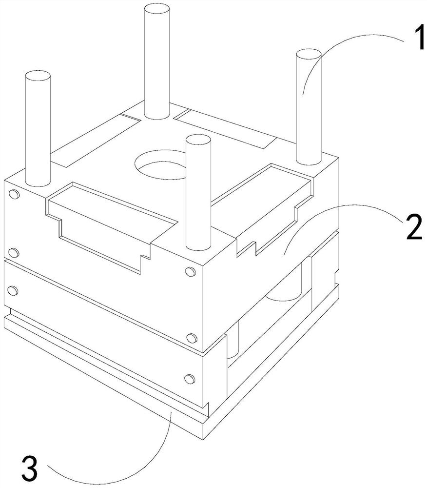
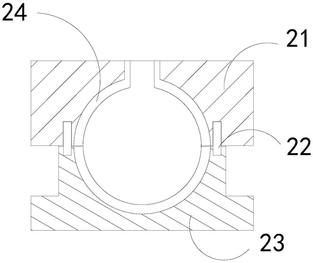
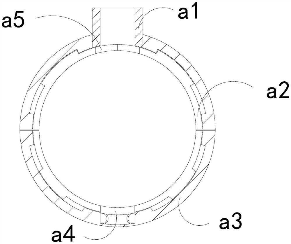
[0026]As for examplefigure 1 -exampleFigure 5 Shown:

[0027]The present invention provides a high-efficiency injection mold opening line. The structure includes an adapter rod 1, a mold 2, and a base 3. The adapter rod 1 is embedded in the upper end position of the mold 2, and the mold 2 and the base 3 are an integrated structure; The mold 2 includes an upper mold 21, a connecting rod 22, a lower mold 23, and an inner cavity 24. The upper mold 21 is connected to the upper end of the lower mold 23 through the connecting rod 22, and the inner cavity 24 is installed in Between the upper connecting mold 21 and the lower connecting mold 23.

[0028]Wherein, the inner cavity 24 includes a feed pipe a1, a bearing plate a2, an outer ring a3, a squeezed block a4, and a contact plate a5. The feed pipe a1 is embedded in the middle of the upper end of the outer ring a3. The bearing plate a2 is movably engaged with the inner side of the outer ring a3, the squeezed block a4 is in clearance fit with th...

Embodiment 2

[0034]As for exampleFigure 6 -exampleFigure 8Shown:

[0035]Wherein, the feed pipe a1 includes an inner contact plate c1, an outer slide plate c2, and an outer frame c3. The inner contact plate c1 and the outer slide plate c2 are an integrated structure, and the outer slide plate c2 and the inner side of the outer frame c3 are movable cards Together, the outer sliding plates c2 are provided with two, and they are evenly distributed symmetrically on the inner side of the outer frame c3, and the outer sliding plate c2 can be forced to slide upward through the extrusion of the inner contact plate c1 by the plastic.

[0036]Wherein, the inner contact plate c1 includes a force plate c11, a re-elastic strip c12, and a receiving plate c13. The force-receiving plate c11 is movably engaged with the right side of the receiving plate c13, and the re-elastic strip c12 is mounted on the receiving plate c13. Between the plate c11 and the receiving plate c13, the force receiving plate c11 is provided wi...


PUM


Abstract

The invention discloses an efficient injection molding mold opening assembly line, which structurally comprises a connecting rod, a mold, and a base, wherein the connecting rod is embedded in and fixed to the position of the upper end of the mold; and the mold and the base are of an integrated structure. When a residual molten plastic raw material on an injection molding pipe drips downwards, a contact plate cannot be pushed to slide; further, the residual molten plastic raw material can be blocked on the upper surface of the contact plate; when the assembly line runs again and the mold is used again, the contact plate is extruded by the molten plastic raw material; the contact plate can be driven by a stress plate to slide and contract; an outer pushing block can be enabled to extend outupwards along an upper placing plate to push away an air-dried plastic layer on the upper surface of the contact plate; the air-dried plastic layer separated from the contact plate is driven by the sliding of the contact plate to extrude the stress plate on an inner contact plate, the stress plate can be enabled to slide upwards; further, the stress plate can be pulled downwards by an elastic strip to slide downwards along a bearing plate; and therefore, the air-dried plastic layer can be clamped and fixed downwards by the stress plate.

Description

Technical field[0001]The invention relates to the field of injection mould opening, in particular to an efficient injection mould opening assembly line.Background technique[0002]The injection mold opening assembly line mold is mainly used for cooling and forming molten plastic raw materials. By continuously conveying the mold to the bottom of the injection molding machine at a constant speed, the injection molding machine can squeeze the molten plastic raw materials into the injection mold in a fixed time. The assembly line mold is a common equipment in the injection mold opening line after the mold is cooled and formed. Based on the above description, the inventor found that the existing high-efficiency injection mold opening line mainly has the following shortcomings, for example:[0003]If the injection molding line is turned off quickly in an emergency during operation, the mold passing under the injection molding machine will stay under the injection molding machine, so that the ...

Claims


Application Information

Patent Timeline
Patent Type & Authority Applications(China)
IPC IPC(8): B29C45/03B29C45/17B29C45/26
CPCB29C45/03B29C45/17B29C45/26
Inventor 陈炳林
Owner 北京林泽荣鑫商贸有限公司
Learn More