Inclined guide groove side core-pulling mold

A side core-pulling and oblique guide groove technology, applied in the field of inclined guide groove side core-pulling molds, can solve the problems of slow speed and inability to combine

Inactive Publication Date: 2020-12-11
北京鸿运汇商贸有限公司
View PDF4 Cites 2 Cited by
  • Summary
  • Abstract
  • Description
  • Claims
  • Application Information

AI Technical Summary

Problems solved by technology

[0003] Since the injection molding speed of the inclined guide groove will be slower than that of the traditional vertical guide groove, so that if the plastic material is injected too fast at one time, the upper thin layer of the plastic material will be air-dried and solidified in advance. If you continue in this state If it enters the mold core, the upper air-dried thin layer cannot be fully combined with the plastic product inside the mold core

Method used


Image

  • Inclined guide groove side core-pulling mold
  • Inclined guide groove side core-pulling mold
  • Inclined guide groove side core-pulling mold

Examples


Embodiment 1

[0026] For example figure 1 -example Figure 5 Shown:

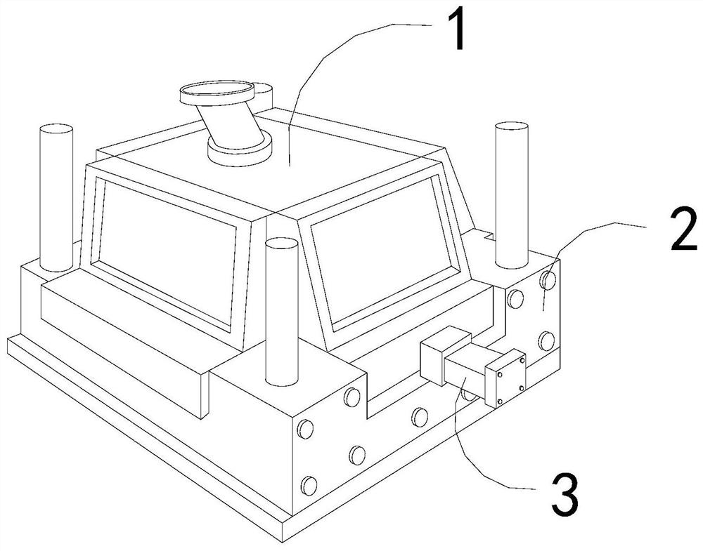
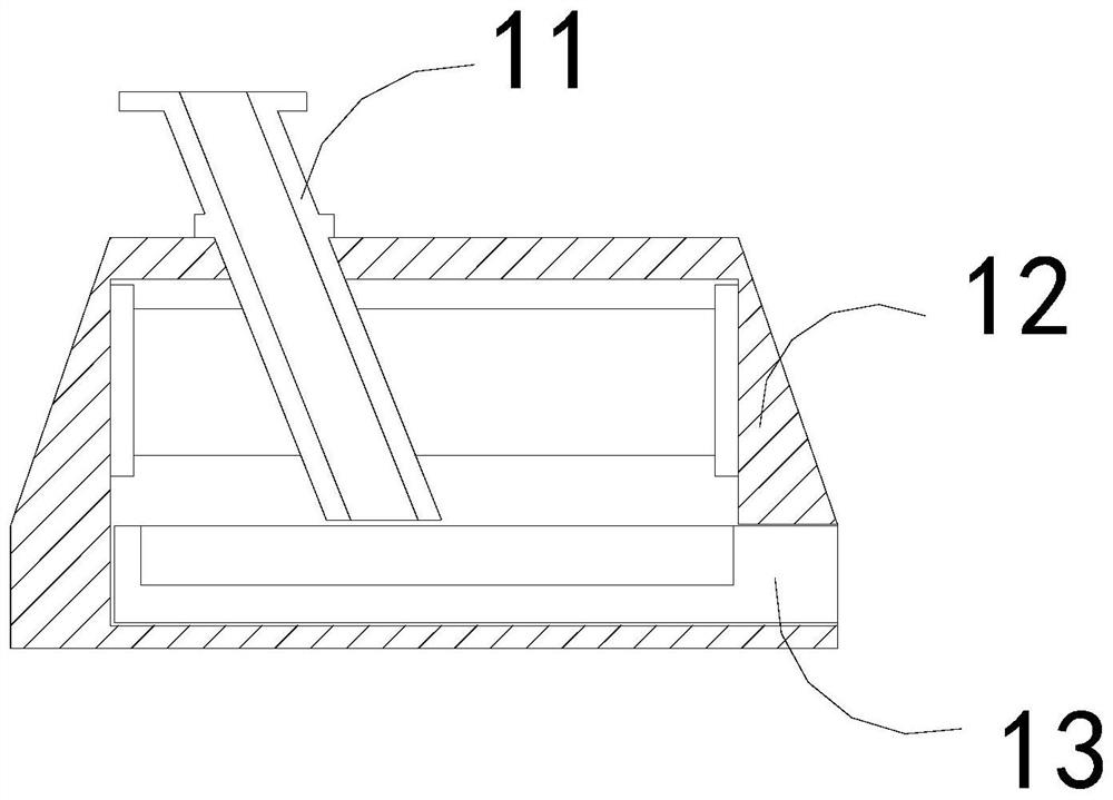
[0027] The present invention provides a core-pulling mold on the side of an inclined guide groove, the structure of which includes a forming cavity 1, a mold base 2, and a pulling handle 3. The pulling handle 3 is embedded in the right side of the forming cavity 1, and the forming cavity 1 and The mold base 2 is an integrated structure; the forming cavity 1 includes an injection molding tube 11, an outer frame 12, and a mold inner core 13. 12 clearance fit.

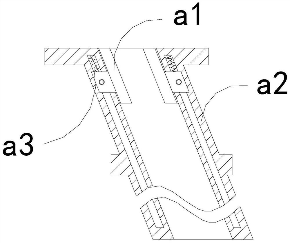
[0028] Wherein, the injection molding tube 11 includes a linkage plate a1, a tube body a2, and a pull-back bar a3, the linkage plate a1 is movably engaged with the tube body a2, and the pull-back bar a3 is installed between the linkage plate a1 and the tube body a2 In between, there are two linkage plates a1, which are evenly distributed symmetrically inside the tube body a2, and the linkage plate a1 can be pulled down along the tube body a2 by the air-dried thin ...

Embodiment 2

[0034] For example Figure 6 -example Figure 8 Shown:

[0035] Wherein, the grip block b3 includes a frame b31, a lower extension plate b32, an adapter frame b33, and a rebound piece b34, the lower extension plate b32 is in clearance fit with the adapter frame b33, and the adapter frame b33 is embedded and connected with the frame b31, The rebound piece b34 is installed between the frame b31 and the connecting frame b33, through the swinging force generated by the mechanism swing, the lower stretching plate b32 can protrude outward along the connecting frame b33, so that the lower stretching plate b32 can be adhered to the A thin layer of residual plastic on the bottom of the object pushes off.

[0036] Wherein, the lower extension plate b32 includes a receiving plate c1, an outer swing rod c2, and a contact plate c3, the outer swing rod c2 is hingedly connected with the receiving plate c1, and the contact plate c3 is connected to the outer end of the outer swing rod c2 Th...


PUM


Abstract

The invention discloses an inclined guide groove side core-pulling mold which structurally comprises a forming cavity, a mold base and a pulling handle, the pulling handle is fixedly embedded in the right side of the forming cavity, the forming cavity and the mold base are of an integrated structure, and when plastic raw materials in a molten state are completely discharged, a linkage plate can bepulled upwards to reset through a pulling-back strip. A lower connecting plate can swing upwards through inertia force generated due to upward sliding of the linkage plate so that a plastic thin layer attached to the bottom of the lower connecting plate can be thrown out upwards through the lower connecting plate, and the situation that the plastic thin layer air-dried in advance can enter the mold is effectively avoided; and through throwing force generated due to swinging of the lower connecting plate, a lower extending plate can extend outwards along a linkage frame, a plastic thin layer left at the bottom of the lower connecting plate can be pushed off, then a removing plate losing extrusion of a frame can be pushed outwards through a middle connecting rod, and therefore the removingplate can eject out a small part of plastics scraped off from the inner wall of the frame.

Description

technical field [0001] The invention relates to the field of molds, in particular to a core-pulling mold on the side of an inclined guide groove. Background technique [0002] The core-pulling mold on the side of the inclined guide groove is mainly used for inverting the plastic with holes or bumps. The molten plastic raw material is injected into the inner core of the mold through the inclined guide groove. Through this injection molding method, the mold can be made The surface of the plastic raw material on the inner core is smoother. Waiting for cooling and solidification, the mold inner core and the plastic product can be pulled out from the side, and then the plastic product is separated from the mold inner core. Based on the above description, the inventors found that the existing A side core-pulling mold with an inclined guide groove mainly has the following deficiencies, for example: [0003] Since the injection molding speed of the inclined guide groove will be slo...

Claims


Application Information

Patent Timeline
Patent Type & Authority Applications(China)
IPC IPC(8): B29C45/17B29C45/44B29C45/33
CPCB29C45/1759B29C45/4435B29C45/33
Inventor 黄炳煌
Owner 北京鸿运汇商贸有限公司
Why Eureka
Try Eureka