Strength detection device for steel preparation

A strength detection and steel technology, applied in the direction of measurement device, strength characteristics, and the use of stable tension/pressure to test the strength of materials, etc., can solve the problems of slipping of steel bars, loose rust layer on the surface of steel bars, errors, etc., to enhance the gripping force , to avoid slippage, to avoid the effect of rust debris that is difficult to clean

Pending Publication Date: 2021-08-27
陈丽娜
View PDF0 Cites 1 Cited by
  • Summary
  • Abstract
  • Description
  • Claims
  • Application Information

AI Technical Summary

Problems solved by technology

[0003] Since the steel bar tensile strength detector pulls the steel bar horizontally through the sliding sleeve inside the pulling tube, if the originally smooth steel bar is oxidized and attached with a thick rust layer, it is easy to appear that the sliding sleeve is pulling the steel bar during the pulling process. The rust layer on the surface is extruded and loosened, causing the steel bar to slip inside the sliding sleeve, so that the tensile strength detector of the steel bar will have errors in the detection of the tensile force of the steel bar

Method used


Image

  • Strength detection device for steel preparation
  • Strength detection device for steel preparation
  • Strength detection device for steel preparation

Examples


Embodiment 1

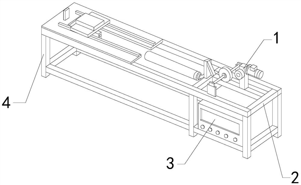
[0028] For example figure 1 -example Figure 5 Shown:

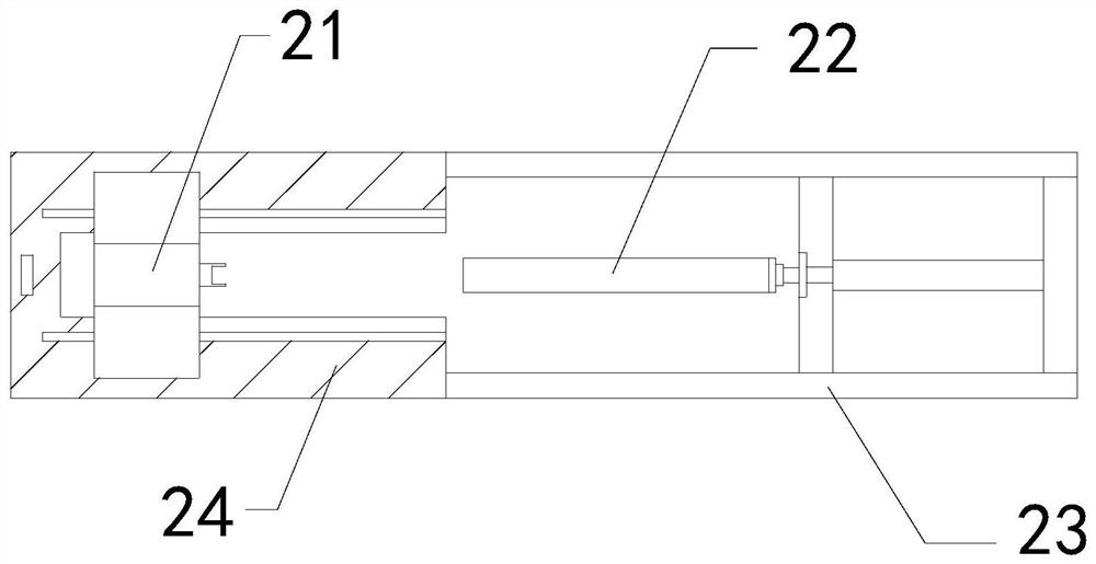
[0029] The invention provides a strength detection device for steel preparation, the structure of which includes a driver 1, an operation table 2, a display table 3, and a support frame 4, the driver 1 is installed on the upper end of the operation table 2, and the display table 3 is embedded in the The inner position of the support frame 4, the bottom of the operating table 2 is welded to the upper end of the supporting frame 4; The frame 21 is installed on the upper surface of the bearing plate 24 , the right side of the pulling tube 22 is connected with the connecting frame 23 , and the left side of the connecting frame 23 is welded with the right side of the supporting plate 24 .

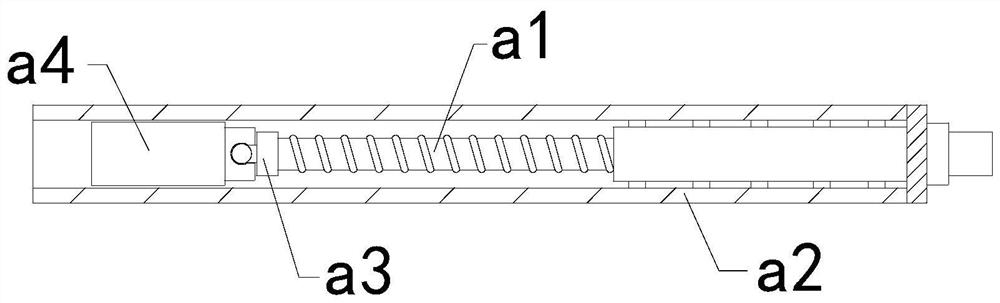
[0030] Wherein, the pulling tube 22 includes a telescopic screw a1, an outer frame a2, a transition block a3, and a sliding sleeve a4, the telescopic screw a1 is connected with the internal thread of the outer frame a2, and the right side...

Embodiment 2

[0036] For example Figure 6 -example Figure 9 Shown:

[0037]Wherein, the sliding sleeve a4 includes a frame c1, a reverse thrust piece c2, an attraction block c3, and a telescopic plate c4, and the reverse thrust piece c2 is installed between the right side of the inner wall of the frame c1 and the right side of the telescopic plate c4. The attracting block c3 is embedded in the inner position of the frame c1, and the side of the telescopic plate c4 slides and fits with the inner wall of the frame c1. The attracting block c3 is made of permanent magnet material, and the steel telescopic plate c4 can be attracted by the attracting block c3. A suction force is generated, so that the telescopic plate c4 can have a magnetic force.

[0038] Wherein, the telescopic plate c4 includes a rear plate c41, a booster bar c42, a linkage rod c43, and a front push plate c44, and the booster bar c42 is installed on the right side of the front push plate c44 and the right side of the inner...


PUM


Abstract

The invention discloses a strength detection device for steel preparation, which structurally comprises a driver, an operation table, a display table and a supporting frame, wherein the driver is installed at the upper end of the operation table, the display table is embedded into the supporting frame, the bottom of the operation table is welded to the upper end of the supporting frame, the inner wall of the frame body extrudes the lower pressing block after a stress plate is expanded outwards, the lower pressing block can slide downwards along a holding and fixing plate, and then the lower pressing block can penetrate through a rust layer on the surface of a reinforcing steel bar, so that the grabbing force to the reinforcing steel bar can be enhanced. After the reinforcing steel bar is taken out, pushing reset of a reverse pushing piece to a telescopic plate is slow due to the attraction force of an attraction block, so that the telescopic plate can continuously adsorb rust scraps in the sliding sleeve. After the telescopic plate is completely pushed away from the attraction block by the reverse pushing piece, a front pushing plate can outwards slide and stretch out along a rear plate under the cooperation of a linkage rod, and then the front pushing plate can pop out the rust scraps attached to the surface of the front pushing plate.

Description

technical field [0001] The invention relates to the technical field of steel preparation, in particular to a strength detection device for steel preparation. Background technique [0002] The steel bar tensile strength detector is mainly used to detect the maximum pulling force that the steel bar can bear. By fixing the steel bar between the position fixing frame and the pulling tube, the steel bar is moved backward through the sliding sleeve inside the pulling tube. Continuous pulling, so as to be able to detect the maximum pulling force that the steel bar can withstand, based on the above description, the inventors found that the existing strength detection device for steel preparation mainly has the following deficiencies, for example: [0003] Since the steel bar tensile strength detector pulls the steel bar horizontally through the sliding sleeve inside the pulling tube, if the originally smooth steel bar is oxidized and attached with a thick rust layer, it is easy to a...

Claims


Application Information

Patent Timeline
Patent Type & Authority Applications(China)
IPC IPC(8): G01N3/08G01N3/04G01N3/02
CPCG01N3/02G01N3/04G01N3/08G01N2203/0019G01N2203/04
Inventor 陈丽娜
Owner 陈丽娜
Why Eureka
Try Eureka