
A qualified inspection device for the production of led fluorescent lamps

A technology of LED fluorescent lamp and detection device, applied in sorting and other directions, can solve the problems of low detection rate, high labor cost, etc., and achieve the effect of preventing fragmentation

Inactive Publication Date: 2021-07-30
深圳市骏欣铝基板有限公司
View PDF0 Cites 0 Cited by
  • Summary
  • Abstract
  • Description
  • Claims
  • Application Information

AI Technical Summary

Problems solved by technology

[0005] In order to overcome the shortcomings of being unable to automatically separate unqualified products, low detection rate, and high labor cost, the technical problem of the present invention is to provide an automatic separation of unqualified LED fluorescent lamps, improve the detection rate, reduce labor costs, and automate the operation process. Qualified inspection device for LED fluorescent lamp production

Method used


Image

  • A qualified inspection device for the production of led fluorescent lamps
  • A qualified inspection device for the production of led fluorescent lamps
  • A qualified inspection device for the production of led fluorescent lamps

Examples


Embodiment 1

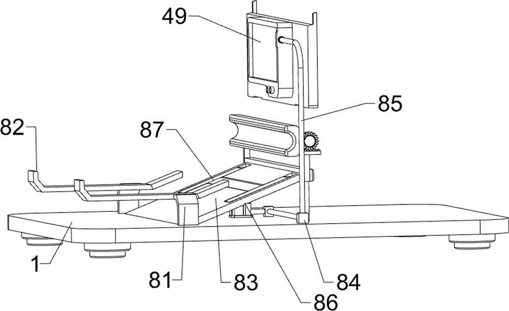
[0080] A qualified detection device for the production of LED fluorescent lamps, such as figure 1 As shown, it includes a base plate 1, a rotating shaft motor 2, a first support column 3, a detection mechanism 4, and a feeding mechanism 5. The rotating shaft motor 2 is connected to the upper right side of the base plate 1, and the first support is connected to the front and rear sides of the upper portion of the base plate 1. The column 3 is connected with a detection mechanism 4 on the upper side of the bottom plate 1 , the detection mechanism 4 is connected with the rotating shaft motor 2 , and the upper side of the bottom plate 1 is connected with a feeding mechanism 5 .

[0081] When the device needs to be used, the user can place the LED light tube in the detection mechanism 4, and then start the rotating shaft motor 2, and the rotating shaft motor 2 reverses to drive the detection mechanism 4 to move to the left, and then drives the detection mechanism 4 to move inward, a...

Embodiment 2

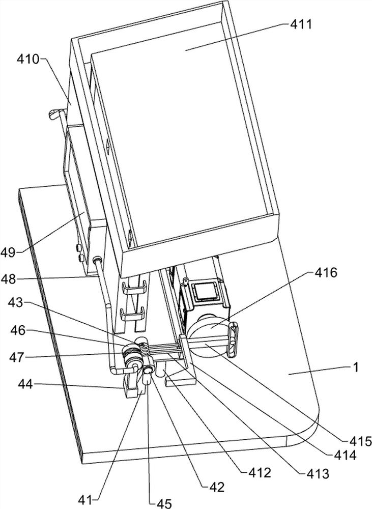
[0083] On the basis of Example 1, such as figure 2 As shown, the detection mechanism 4 includes a second support column 41, a first slide bar 42, a first spring 43, a connecting rod 44, a first push rod 45, a contact block 46, a second spring 47, a first electric wire 48, a display 49. Guide plate 410, blanking basket 411, third support column 412, slide rail 413, second ejector rod 414, second slide bar 415 and turntable 416, the upper and lower sides of bottom plate 1 are connected with second support column 41 , the first sliding rod 42 is slidably connected to the second support column 41, the connecting rod 44 is connected to the first sliding rod 42, the first spring 43 is wound on the first sliding rod 42, and the first spring 43 is located at The inner side of the connecting rod 44 and the lower side of the connecting rod 44 are connected with the first push rod 45, and the connecting rod 44 is connected with the contact block 46 in a sliding manner, and the contact b...


PUM


Abstract

The invention relates to a qualified detection device, in particular to a qualified detection device for the production of LED fluorescent lamps. The purpose of the present invention is to provide a qualified detection device for LED fluorescent lamp production that can automatically separate unqualified LED fluorescent lamps, improve the detection rate, reduce labor costs, and automate the operation process. The technical solution of the present invention is: a qualified detection device for the production of LED fluorescent lamps, comprising: a rotating shaft motor connected to one side of the top of the bottom plate; a first support column connected to both sides of the top of the bottom plate; a detection mechanism , a detection mechanism is connected to the top side of the bottom plate, and the detection mechanism is connected to the rotating shaft motor; a feeding mechanism is connected to a feeding mechanism on the top side of the bottom plate. In the present invention, through the cooperation of the connecting rod, the display, the blanking basket and the turntable, the purpose of fastening the LED lamp tubes and performing qualified inspection on the LED lamp tubes is achieved.

Description

technical field [0001] The invention relates to a qualified detection device, in particular to a qualified detection device for the production of LED fluorescent lamps. Background technique [0002] Compared with incandescent lamps, LED fluorescent lamps save more than 80% of electricity, and their lifespan is more than 10 times that of ordinary lamps. They are almost maintenance-free, and there is no problem of frequent replacement of lamp tubes and starters. The cost can be exchanged, so LED fluorescent lamps are more commonly used and have a wider range of applications. [0003] After the LED fluorescent tube is produced, it needs to be energized and aging tested before leaving the factory to ensure the quality of the factory-made tube products. The long-term aging test of LED fluorescent lamps and lighting products is a very important test. Passing the aging test can ensure early Finding possible failures such as light decay, color temperature change, and leakage of LED...

Claims


Application Information

Patent Timeline
Patent Type & Authority Patents(China)
IPC IPC(8): B07C5/344
CPCB07C5/344
Inventor 赖学良赖致升
Owner 深圳市骏欣铝基板有限公司
Learn More