
Variable flow rate valve mechanism and supercharger

A valve mechanism and variable technology, applied in the direction of machines/engines, connecting components, mechanical equipment, etc., can solve the problems of spring washer elasticity deterioration and elasticity deterioration, and achieve the effect of suppressing elasticity deterioration

Active Publication Date: 2021-02-02
IHI CORP
View PDF6 Cites 0 Cited by
  • Summary
  • Abstract
  • Description
  • Claims
  • Application Information

AI Technical Summary

Problems solved by technology

However, if the deformation of the spring washer is too large, the elasticity of the spring washer may be deteriorated
That is, the spring washer has a tendency to extend radially when subjected to an axial force, and such deformation leads to poor elasticity (so-called "deformation")

Method used


Image

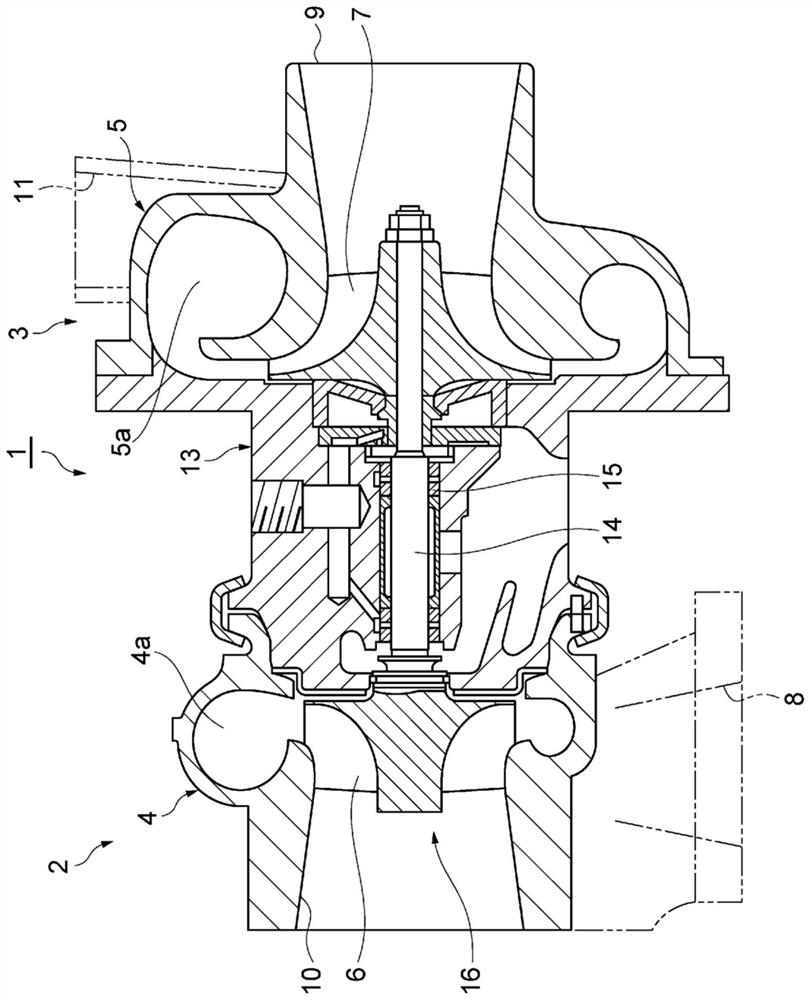
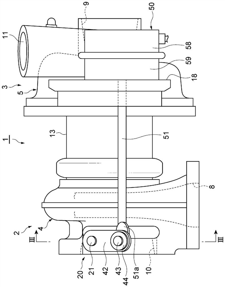
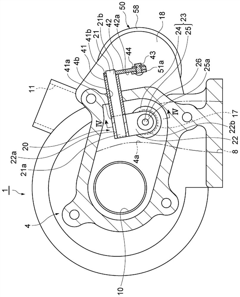
  • Variable flow rate valve mechanism and supercharger
  • Variable flow rate valve mechanism and supercharger
  • Variable flow rate valve mechanism and supercharger

Examples


Embodiment Construction

[0020] A variable flow valve mechanism according to one aspect of the present disclosure includes: a valve including a valve body and a valve shaft protruding from the valve body and having an axis; a stopper member fixed to the valve shaft at a position separated from the valve body in the axial direction; A mounting part, which is arranged between the valve body and the stopper, holds the valve together with the stopper; and a spring washer, which is arranged between the stopper and the installation part, or between the installation part and the valve body, and serves as The stopper part or the first part of the valve body is in contact with the second part as the installation part to apply elastic force to the installation part. The spring washer includes an outer peripheral part in contact with either the first part or the second part. Either one of the second member and the second member is formed with an inner surface facing radially inward and facing the outer peripheral...


PUM


Abstract

A variable flow rate valve mechanism comprises: a valve that includes a valve body and a valve shaft protruding from the valve body; a fixing member that is fixed to the valve shaft at a position awayfrom the valve body in the axial direction; an installing member that is provided between the valve body and the fixing member and, with the fixing member, retains the valve; and a spring washer thatis provided between the fixing member and the installing member or the installing member and the valve body and that provides elasticity for the installing member in contact with the fixing member orvalve body and the installing member. A first member or a second member has an inner surface formed to face radially inward and face the outer circumferential section of the spring washer.

Description

technical field [0001] The present disclosure relates to a variable flow valve mechanism and a supercharger. Background technique [0002] Conventionally, a valve structure for opening and closing an exhaust gas bypass opening formed in a turbine casing is known for a turbine of a supercharger. In the structure described in Patent Document 1, an annular spring member is arranged between a valve support member through which the shaft of the valve body passes and a gasket. In the structure described in Patent Document 2, an elastic element (spring member) is disposed between the shutter and the rod, or between the rod and the disk. The resilient element reduces or prevents possible wear at the point of contact between the two components. [0003] Patent Document 1: Specification of US Patent No. 9127590 [0004] Patent Document 2: Japanese National Publication No. 2012-527575 [0005] As mentioned above, the spring member (spring washer) is arranged between the two members...

Claims


Application Information

Patent Timeline
IPC IPC(8): F02B37/18F16B39/24F16B43/00
CPCY02T10/12F02B37/183F05D2220/40F05D2240/70F05D2260/606
Inventor 许宰珉
Owner IHI CORP
Learn More