Driving method of display substrate, display substrate and display device

A technology of display substrate and driving method, which is applied in the direction of instruments, lenses, optical components, etc., and can solve the problems of thick and heavy display equipment

Active Publication Date: 2021-02-05
FUZHOU BOE OPTOELECTRONICS TECH CO LTD +1
View PDF5 Cites 1 Cited by
  • Summary
  • Abstract
  • Description
  • Claims
  • Application Information

AI Technical Summary

Problems solved by technology

[0003] The existing full-screen products all need to install a front camera on the

Method used


Image

  • Driving method of display substrate, display substrate and display device
  • Driving method of display substrate, display substrate and display device
  • Driving method of display substrate, display substrate and display device

Examples


Embodiment Construction

[0040] In order to make the above objects, features and advantages of the present invention more comprehensible, the present invention will be further described in detail below in conjunction with the accompanying drawings and specific embodiments.

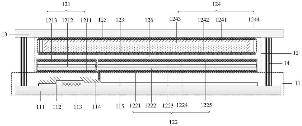
[0041] An embodiment of the present application provides a display substrate, referring to figure 1 , the display substrate includes: a base substrate 11 and one or more discrete camera units 12 disposed on one side of the base substrate 11 .

[0042] Each imaging unit 12 includes: one or more pixel units arranged on one side of the base substrate 11, and a first electrode 123, a liquid microlens 124 and The second electrode 125, the first electrode 123 and the second electrode 125 are used to form the driving voltage applied to the liquid microlens 124, and the liquid microlens 124 is used to change its own focal length when the driving voltage changes, so that the display substrate works in the display. state or imaging state; ...


PUM


Abstract

The invention provides a driving method of a display substrate, the display substrate and a display device. The display substrate comprises a substrate body and one or more discrete camera units arranged on one side of the substrate body. Each camera unit comprises one or more pixel units arranged on one side of the underlayer substrate, and a first electrode, a liquid micro lens and a second electrode which are stacked on one side, deviating from the underlayer substrate, of the one or more pixel units, and the first electrode and the second electrode are used for forming a driving voltage applied to the liquid micro lens; the liquid micro lens is used for changing the focal length of the liquid micro lens when the driving voltage changes, so that the display substrate works in a displaystate or a camera shooting state; each pixel unit comprises a photosensitive unit and a light-emitting unit, and the photosensitive unit is used for carrying out photoelectric conversion on light emitted from the liquid micro lens. The liquid micro lens and the photosensitive unit are integrated in the display substrate, the shooting function can be achieved, the normal display function can also be achieved, and the display device is light and thin.

Description

technical field [0001] The present invention relates to the field of display technology, in particular to a method for driving a display substrate, a display substrate and a display device. Background technique [0002] With the improvement of people's aesthetics, full-screen display will become the development trend of mobile phone screens in the future. In recent years, full-screen forms such as lifting cameras, Qi Liu Hai, and water drop screens are all pursuing beautiful terminal shapes. [0003] Existing full-screen products all need to install a front-facing camera on the screen, and the installation of the camera makes the display device relatively thick. Contents of the invention [0004] The invention provides a method for driving a display substrate, a display substrate and a display device, so as to reduce the weight and thickness of the display device. [0005] In order to solve the above problems, the present invention discloses a display substrate, which in...

Claims


Application Information

Patent Timeline
IPC IPC(8): H01L27/32G02B3/14G02B26/00G02B26/08H04M1/02
CPCG02B3/14G02B26/004G02B26/0875H04M1/0266H10K59/00H10K59/60H10K59/12
Inventor 石常洪王进吴振钿刘祖文邱鑫茂吕耀朝陶文昌林剑涛洪贵春刘耀钟娴程浩
Owner FUZHOU BOE OPTOELECTRONICS TECH CO LTD
Why Eureka
Try Eureka