Display panel and display device

A technology of display panel and display area, which is applied to static indicators, instruments, semiconductor devices, etc., and can solve the problems of display panel split screen and large difference in impedance of adjacent fan-out lines.

Active Publication Date: 2021-02-09
XIAMEN TIANMA MICRO ELECTRONICS
View PDF10 Cites 1 Cited by
  • Summary
  • Abstract
  • Description
  • Claims
  • Application Information

AI Technical Summary

Problems solved by technology

[0004] The embodiment of the present invention provides a display panel and a display device, which solves the problem of split screens in the display panel due to the great difference in the impedance of some adjacent fan-out lines in the prior art

Method used


Image

  • Display panel and display device
  • Display panel and display device
  • Display panel and display device

Examples


Embodiment Construction

[0028] In order to make the purpose, technical solution and advantages of the present invention clearer, the technical solution of the present invention will be fully described below through specific implementation in combination with the drawings in the embodiments of the present invention. Apparently, the described embodiments are some embodiments of the present invention, rather than all embodiments. Based on the embodiments of the present invention, all other embodiments obtained by persons of ordinary skill in the art without making creative efforts, All fall within the protection scope of the present invention.

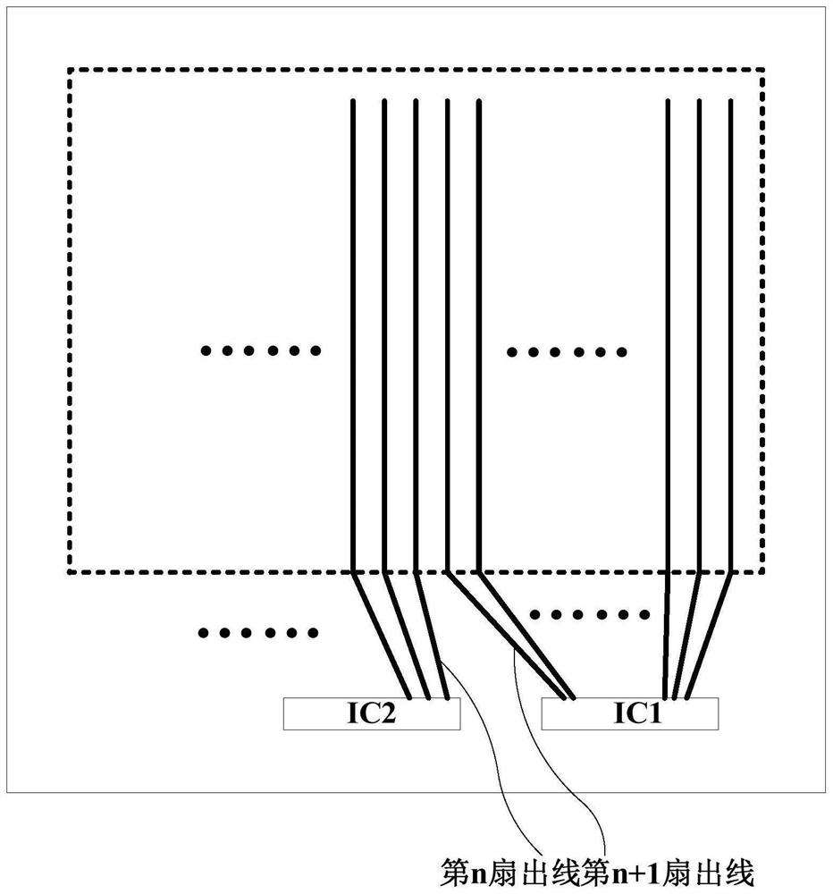
[0029] figure 1 It is a structural schematic diagram of a display panel in the prior art, such as figure 1 shown, including multiple driver chips, figure 1 In the example, two driver chips are set, namely driver chip IC1 and driver chip IC2. The driving chip IC1 is adjacent to the driving chip IC2. Each signal line in the display area needs to be electricall...


PUM


Abstract

The invention discloses a display panel and a display device. The adjacent sub-binding areas of the display panel are respectively a first sub-binding area and a second sub-binding area; the fan-out line correspondingly and electrically connected with the binding bonding pad nearest to the second sub-binding area in the first sub-binding area is the ith fan-out line; the fan-out line correspondingly and electrically connected with the binding bonding pad nearest to the first sub-binding area in the second sub-binding area is the jth fan-out line; the jth fan-out line comprises a jth straight line section; the ith fan-out line comprises an ith broken line section; the included angle between the first part of the ith broken line section and the jth straight line section is smaller than a first included angle threshold value, and the difference between the included angle between the second part of the ith broken line section and the second direction and the included angle between the jthstraight line section and the second direction is smaller than a second included angle threshold value; the length difference value of the jth straight line section and the ith broken line section issmaller than a preset length value; and the included angle between the first part and the second part of each fan-out line comprising the first part and the second part is gradually increased along the direction deviating from the second sub-binding area.

Description

technical field [0001] Embodiments of the present invention relate to the field of display technology, and in particular, to a display panel and a display device. Background technique [0002] In a conventional display device, the driver chip needs to provide signals to the display area of ​​the display panel through fan-out lines, so as to drive the display panel for display. [0003] Due to the location of the driver chip and the signal lines in the display area, the lengths of the fan-out lines from the output pins of the driver chip to the signal lines in the display area are different. Especially when multiple driver chips are installed, the impedance of each fan-out line corresponding to the same driver chip is slightly different, but the impedance of two adjacent fan-out lines of adjacent driver chips is very different, and there is a sudden change in impedance, which makes the transmitted signal waveform serious. Distortion, resulting in problems such as split scree...

Claims


Application Information

Patent Timeline
Patent Type & Authority Applications(China)
IPC IPC(8): H01L25/18G09G3/20
CPCH01L25/18G09G3/20
Inventor 邹宗骏孙莹许育民
Owner XIAMEN TIANMA MICRO ELECTRONICS
Why Eureka
Try Eureka