Floating type connector structure

A connector and floating technology, which is applied to the parts, connections, electrical components, etc. of the connection device, can solve the problems of connector damage, poor contact at the connector connection, loss, etc., to increase the insertion stability, Avoid breaking loss and prolong service life

Pending Publication Date: 2021-02-09
台铃科技(江苏)股份有限公司
View PDF0 Cites 0 Cited by
  • Summary
  • Abstract
  • Description
  • Claims
  • Application Information

AI Technical Summary

Problems solved by technology

[0002] At present, the connectors that are electrically connected between the battery and the seat barrel of electric vehicles and other vehicles are common plug-in structures in which the male head is connected to the female seat. There is shaking in the battery of electric vehicles, and the connection of the connectors is prone to occur during the shaking process due to physical problems. Poor contact or breakage caused by impact will cause destructive loss of connectors and seriously affect the service life and stability of connectors

Method used


Image

  • Floating type connector structure
  • Floating type connector structure
  • Floating type connector structure

Examples


Embodiment Construction

[0017] The specific implementation manner of the present invention will be described below in conjunction with the accompanying drawings.

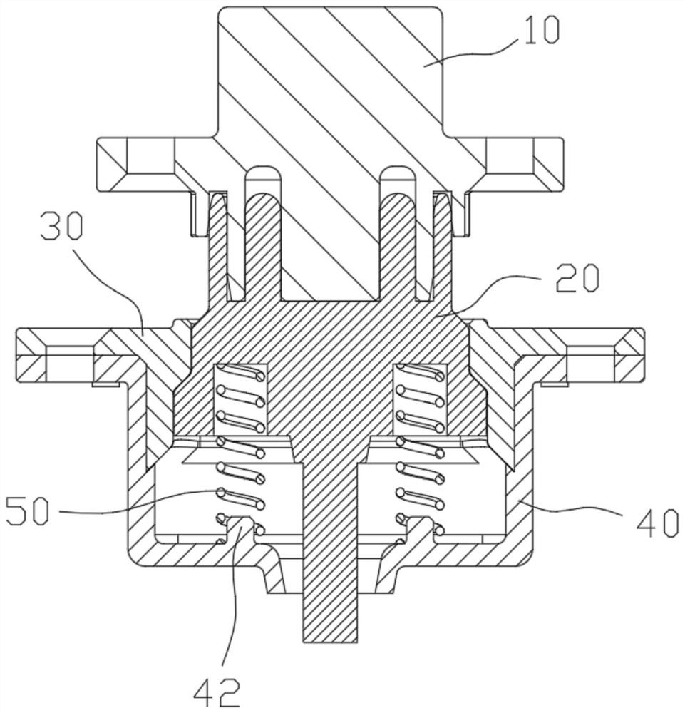
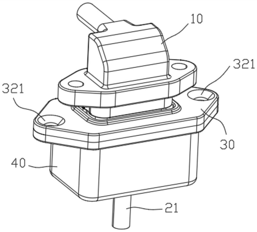
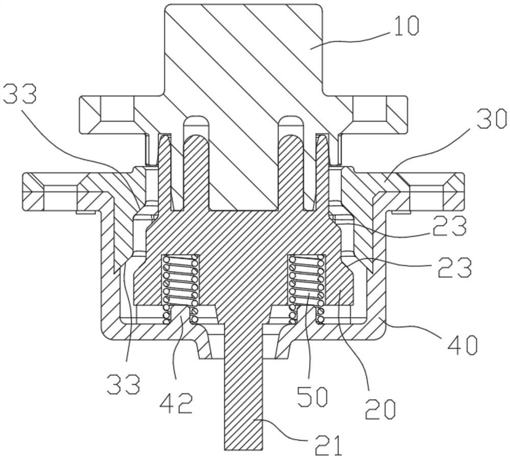
[0018] Such as Figure 1-6 As shown, the floating connector structure of the present embodiment includes a connector male 10, a connector female seat 20, an upper housing 30, a lower housing 40 and a spring 50, the lower housing 40 is an open box shape, and the upper housing The body 30 includes four surrounding walls 31, the upper housing 30 is detachably inserted and fixed at the box port of the lower housing 40, the lower half of the connector female seat 20 is arranged in the box of the lower housing 40, and the connector female seat 20 The spring 50 is connected between the lower end and the bottom surface of the inner box of the lower housing 40 to realize the bouncing of the connector female seat 20, and the structure between the upper housing 30 and the connector female seat 20 prevents the connector female seat 20 from the lower h...


PUM


Abstract

The invention relates to the technical field of connectors, in particular to a floating connector structure, which is characterized in that a lower shell is in an open box shape, an upper shell comprises peripheral walls, the upper shell is detachably inserted and fixed in a box port of the lower shell, and the lower half part of a connector female seat is arranged in a box of the lower shell; thelower end of the connector female seat is connected with the bottom surface of the inner box of the lower shell through a spring to achieve springing of the connector female seat, limiting fit for preventing the connector female seat from springing out of the lower shell is formed between the upper shell and the connector female seat, and a socket of the connector female seat extends out of the lower shell in an overhanging mode. A connector male head and the connector female seat form plugging cooperation. A through hole is formed in the middle of the box bottom of the lower shell, a wire inthe middle of the lower end of the connector female seat extends out of the through hole, and after the connector male head is pressed downwards to be connected with the connector female seat in an inserted mode, a spring is pressed downwards, so that enough shaking adjusting gaps exist around the connector female seat. The plugging stability of the connector is improved, and the service life ofthe connector is prolonged.

Description

technical field [0001] The invention relates to the technical field of connectors, in particular to a floating connector structure. Background technique [0002] At present, the electric connection between the battery and the seat barrel of the electric vehicle and other vehicles is a common plug-in structure with the male head connected to the female seat. The battery of the electric vehicle shakes, and the connection of the connector is prone to occur during the shaking process due to physical damage. The poor contact or breakage caused by the impact will cause destructive loss of the connector and seriously affect the service life and stability of the connector. Contents of the invention [0003] Aiming at the above-mentioned shortcomings in the existing production technology, the applicant provides a floating connector structure, which can increase the insertion stability of the connector and prolong the service life of the connector. [0004] The technical scheme ado...

Claims


Application Information

Patent Timeline
Patent Type & Authority Applications(China)
IPC IPC(8): H01R13/502H01R13/533H01R24/20H01R24/28
CPCH01R13/502H01R13/533H01R24/20H01R24/28
Inventor 孙木楚
Owner 台铃科技(江苏)股份有限公司
Why Eureka
Try Eureka