Automatic grabbing and aligning device

An automatic, rotating rod technology, applied in the direction of measuring device, mechanical device, mechanical measuring device, etc., can solve the problems of no transmission function, limited size detection of the compression spring, etc., to achieve easy transmission, increase in length and simple structure. Effect

Active Publication Date: 2021-02-19
WUXI KAILUNA SPRING
View PDF15 Cites 0 Cited by
  • Summary
  • Abstract
  • Description
  • Claims
  • Application Information

AI Technical Summary

Problems solved by technology

[0004] The purpose of the present invention is to solve the shortcomings of the existing automatic grasping and aligning device, which has no better transmission function, and the scale of the size detection of the pressure spring is limited, and proposes an automatic grasping and aligning device

Method used


Image

  • Automatic grabbing and aligning device
  • Automatic grabbing and aligning device
  • Automatic grabbing and aligning device

Examples


Embodiment 1

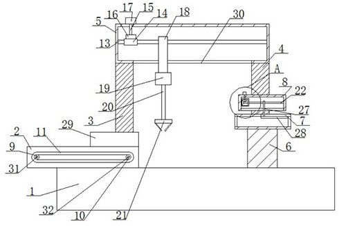
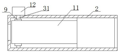
[0026] refer to Figure 1-5 , the automatic grasping and aligning device includes a base 1, a transmission base 2 is fixedly installed on the top of the base 1, a first support column 3 and a second support column 4 are fixedly installed on the top of the base 1, the first support column 3 and the second support column One end of the support column 4 is fixedly installed with the same top frame 5, the bottom of the top frame 5 is provided with a first long hole 30, the top of the base 1 is fixedly installed with a pillar 6, and the top of the pillar 6 is fixedly installed with a scale cylinder 7, the scale cylinder The top of 7 is slidingly connected with a scale 28, and one side of the second support column 4 is fixedly installed with a drive frame 8, and the drive frame 8 is rotatably connected with a second screw rod 22, and one end of the second screw rod 22 is fixedly connected with a first bevel gear 23. The second screw rod 22 is threadedly connected with a second movin...

Embodiment 2

[0035] refer to Figure 1-5 , the automatic grasping and aligning device, including a base 1, the top of the base 1 is welded with a transmission seat 2, the top of the base 1 is welded with a first support column 3 and a second support column 4, the first support column 3 and the second One end of the support column 4 is welded with the same top frame 5, the bottom of the top frame 5 is provided with a first long hole 30, the top of the base 1 is welded with a pillar 6, and the top of the pillar 6 is welded with a scale cylinder 7, the scale cylinder The top of 7 is slidingly connected with a scale 28, and one side of the second support column 4 is welded with a drive frame 8, and the drive frame 8 is rotatably connected with a second screw 22, and one end of the second screw 22 is welded with a first bevel gear 23. The second screw rod 22 is threadedly connected with a second moving plate 27, and one side of the second moving plate 27 is provided with a second threaded hole,...


PUM


Abstract

The invention belongs to the technical field of automatic grabbing and aligning, particularly relates to an automatic grabbing and aligning device, which aims at solving the problems that an existingautomatic grabbing and aligning device does not have a better conveying function, and the size detection scale of a compressed spring is limited. Theautomatic grabbing and aligning device in the scheme comprises a base, a conveying seat is fixedly arranged on the top of the base, a first supporting column and a second supporting column are fixedly installed at the top of the base, the same top frame is fixedly installed at one end of the first supporting column and one end of the second supporting column, a first long hole is formed in the bottom of the top frame, a supporting column is fixedly installed at the top of the base, a scale cylinder is fixedly installed at the top of the supporting column and slidably connected with the top of the scale cylinder, a driving frame is fixedly mounted on one side of the second supporting column, and a second screw rod is rotatably connected into the driving frame. The device is simple in structure, the compressed spring is conveniently conveyed, the length of the graduated scale can be increased, and people can use the device conveniently.

Description

technical field [0001] The invention relates to the technical field of automatic grasping alignment and automatic grasping alignment, in particular to an automatic grasping alignment device. Background technique [0002] The size and appearance inspection device of the compression spring needs to transfer the compression spring from one device to another for detection, and perform size detection on the compression spring. During the transmission, it is necessary to manually correct and align the compression spring, which takes a lot of time and effort. [0003] The existing automatic grasping and aligning device does not have a better transmission function, and the size detection scale of the compression spring is limited. Contents of the invention [0004] The purpose of the present invention is to solve the shortcomings of the existing automatic grasping and aligning device, which has no better transmission function and the scale of the size detection of the pressure sp...

Claims


Application Information

Patent Timeline
Patent Type & Authority Applications(China)
IPC IPC(8): G01B5/00
CPCG01B5/0004G01B5/00
Inventor 周文胜李杰邱波
Owner WUXI KAILUNA SPRING
Why Eureka
Try Eureka