A telescopic gate

A telescopic, barrier technology, applied in the directions of roads, roads, road signs, etc., can solve the problems of barrier and vehicle damage, slow opening and closing, inapplicability, etc. Faster and more efficient

Active Publication Date: 2022-08-09
深圳市财门智能科技有限公司
View PDF7 Cites 0 Cited by
  • Summary
  • Abstract
  • Description
  • Claims
  • Application Information

AI Technical Summary

Problems solved by technology

[0002] Barrier gates will be set up at the intersections where trains pass and the roads in front of some schools to restrict the passage of vehicles. The more common barrier gates are usually swing arm barrier gates and mobile barrier gates. The length of the arm is not suitable for wider road use, and the mobile barrier gate, which opens and closes slowly, is not suitable for wider road use
[0003] In order to ensure the smoothness of the road and realize the opening and closing of wider roads at the fastest speed, a hydraulic lifting barrier has appeared on the market. The hydraulic cylinder is embedded in the ground, and when the road is closed, the hydraulic column is driven to extend out. , to close the road, but because there is a visual blind spot directly in front of the vehicle, when the vehicle stops too close to the switch, it is impossible to see whether the barrier is fully retracted. Start the vehicle while retracting and hit the barrier, causing damage to both the barrier and the vehicle
[0004] Secondly, the hydraulic lift type barrier gate needs to provide power when it is raised and retracted, and compared with the swing arm type and mobile barrier gate, the energy consumption will be larger, and there is a demand for energy saving. Moreover, in daily use, some drivers have an adventurous heart and want to accelerate and rush past the barrier gate when it is about to rise or is not fully raised. At this time, the impact fails and a larger accident will occur.

Method used


Image

  • A telescopic gate
  • A telescopic gate
  • A telescopic gate

Examples


Embodiment Construction

[0019] The technical solutions in the embodiments of the present invention will be clearly and completely described below with reference to the accompanying drawings in the embodiments of the present invention. Obviously, the described embodiments are only a part of the embodiments of the present invention, but not all of the embodiments. Based on the embodiments of the present invention, all other embodiments obtained by those of ordinary skill in the art without creative efforts shall fall within the protection scope of the present invention.

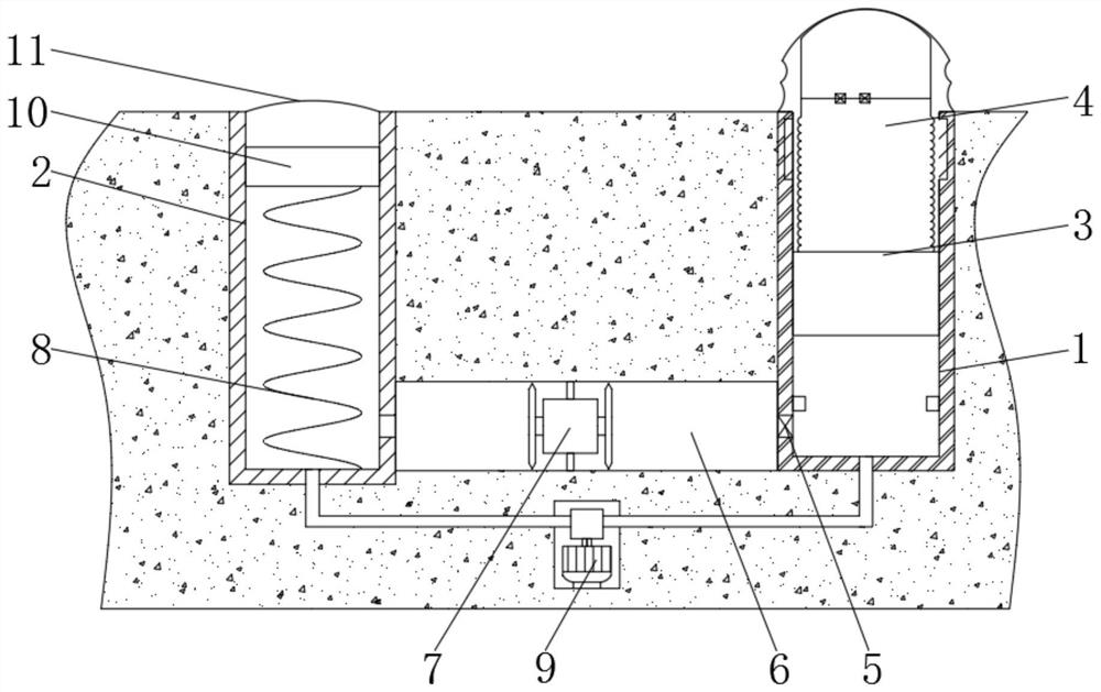
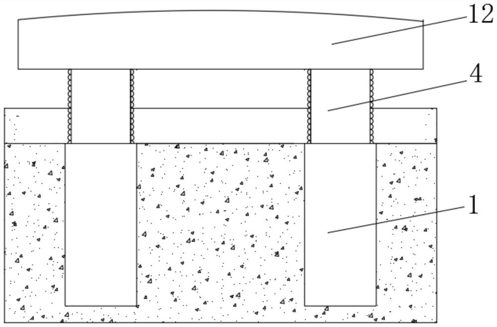
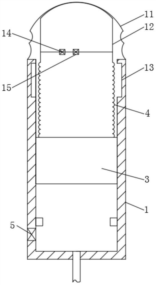
[0020] see figure 1 , a telescopic gate, including a drive cylinder 1 and an accumulator cylinder 2 embedded in the intersection, the accumulator cylinder 2 is located in the direction of the car coming from the drive cylinder 1, the drive cylinder 1 and the accumulator cylinder 2 are both pneumatic cylinders, and the drive cylinder 1 is equipped with a plunger 3, the upper end of the plunger 3 is provided with a flexible material and...


PUM


Abstract

The present invention involves the field of municipal equipment technology, and a telescopic gate is disclosed, including the driver and storage cylinder embedded in the intersection.Insida.Because the extended part is composed of compressed deformed columns and plunges, when the overall shrinking road surface, when the top hour of the identifier column is in the visual blind area of the car, the plunger is already lower than the chassis. At this timeIt will only compress the identification column deformation. On the other hand, the pillow sac is higher than the pavement. The swelling plastic fluid within it can play a speed limit and effectively avoid the driver's acceleration of the driver.The response speed is faster, and the extreme time can drive the plunger and identify the column to shrink back, further reducing the chance of the identification column and the plunger that has not been retracted in time to collide with the vehicle.Can use residual dynamic or potential energy for power generation.

Description

technical field [0001] The invention relates to the technical field of municipal equipment, in particular to a telescopic gate. Background technique [0002] Barriers will be set up at the intersections where trains pass and on the roads in front of some schools to restrict the passage of vehicles. The more common barriers are usually swing arm barriers and mobile barriers. Swing arm barriers are the most common, but restricted and pendulum The length of the arm is not suitable for wider road use, and the mobile barrier, which opens and closes slowly, is not suitable for wider road use. [0003] In order to ensure the normality of the road and realize the opening and closing of the wider road at the fastest speed, a hydraulic lift gate has appeared on the market. The hydraulic cylinder is embedded in the ground. When the road is closed, the hydraulic column is driven to extend. , to close the road. However, because there is a blind spot in front of the vehicle, when the veh...

Claims


Application Information

Patent Timeline
Patent Type & Authority Patents(China)
IPC IPC(8): E01F13/04E01F9/608F01D15/10
CPCE01F13/046E01F9/608F01D15/10Y02E70/30
Inventor 赵娟
Owner 深圳市财门智能科技有限公司
Why Eureka
Try Eureka