
Speed limiting device of wind driven generator

A technology of wind power generator and speed limiting device, which is applied in the direction of wind power generator, control of wind power generator, wind power generation, etc. It can solve the problems of not being able to know the operation status of the generator, interruption of power generation, and affecting the service life of power generation equipment, etc.

Pending Publication Date: 2021-12-24
BEIJING HUANENG XINRUI CONTROL TECH
View PDF0 Cites 0 Cited by
  • Summary
  • Abstract
  • Description
  • Claims
  • Application Information

AI Technical Summary

Problems solved by technology

[0002] Wind power generation usually uses wind to drive the fan blades to rotate, and converts the power of the fan blade drive shaft into mechanical energy, and realizes the process of generating electricity through the generator. In the process of wind power generation, because the speed of the drive shaft is not uniform, and the generator's Overload will cause power generation interruption, which will affect the service life of power generation equipment. Therefore, when the generator is used, it is necessary to set up a structure to limit its speed
[0003] At present, most of the traditional speed limiting devices use the method of adding rubber pads to contact the drive shaft to increase the friction to limit the speed. However, the friction between the drive shaft and the rubber pad for a long time will not only cause rapid wear of the rubber pad, Affect the effect of speed limit, and also generate a certain amount of heat, which will affect the operation of the generator
Moreover, most of the traditional speed limiting devices are manually controlled on the speed limiting structure, which is used to limit the speed of the generator. Since the wind power generation equipment is in a relatively high position, it is impossible to know the operation of the generator when adjusting the speed limiting structure. , when the generator is in an overload state, it is impossible to know immediately and take corresponding measures

Method used

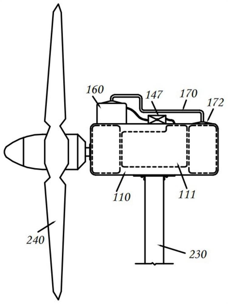
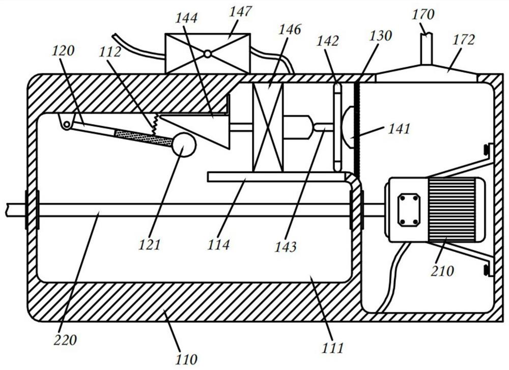
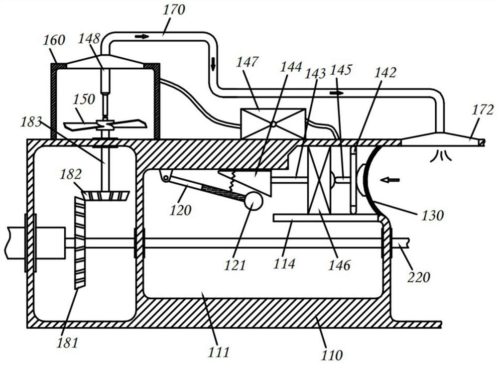

Image

  • Speed limiting device of wind driven generator
  • Speed limiting device of wind driven generator
  • Speed limiting device of wind driven generator

Examples


Embodiment Construction

[0035] In order to enable those skilled in the art to better understand the technical solutions of the present invention, the present invention will be further described in detail below in conjunction with the accompanying drawings and specific embodiments. Apparently, the described embodiments are some, not all, embodiments of the present invention. Based on the described embodiments of the present invention, all other embodiments obtained by persons of ordinary skill in the art without creative efforts shall fall within the protection scope of the present invention.

[0036] Unless otherwise specified, the technical terms or scientific terms used in the present invention shall have the usual meanings understood by those skilled in the art to which the present invention belongs. "Include" or "comprising" used in the present invention neither limit the mentioned shapes, numbers, steps, actions, operations, components, elements and / or their groups, nor exclude the occurrence or...


PUM


Abstract

The invention provides a speed limiting device of a wind driven generator, and belongs to the technical field of wind power generation. The speed limiting device of the wind driven generator comprises a device box, a magnetic speed limiting piece, a sealing piece and a driving assembly, and the magnetic speed limiting piece, the sealing piece and the driving assembly are accommodated in the device box. The sealing piece is located between the generator and the device box, so that the sealing piece is heated to expand towards one side of the driving assembly after the generator generates high temperature; and one end of the driving assembly is connected with the sealing piece, the other end of the driving assembly is connected with the magnetic speed limiting piece, so that the sealing piece expands to drive the magnetic speed limiting piece to be close to a driving shaft of the generator, speed limiting is carried out on the driving shaft through magnetic force, the rotating resistance of the driving shaft is increased, and the speed limiting effect is achieved. Compared with a traditional speed limiting mode, manual contact is not needed for speed limiting adjustment in the aspect.

Description

technical field [0001] The invention belongs to the technical field of wind power generation, and in particular relates to a speed limiting device for a wind power generator. Background technique [0002] Wind power generation usually uses wind to drive the fan blades to rotate, and converts the power of the fan blade drive shaft into mechanical energy, and realizes the process of generating electricity through the generator. In the process of wind power generation, because the speed of the drive shaft is not uniform, and the generator's Overload will cause interruption of power generation, which in turn will affect the service life of power generation equipment. Therefore, when the generator is in use, it is necessary to set up a structure to limit its speed. [0003] At present, most of the traditional speed limiting devices use the method of adding rubber pads to contact the drive shaft to increase the friction to limit the speed. However, the friction between the drive s...

Claims


Application Information

Patent Timeline
Patent Type & Authority Applications(China)
IPC IPC(8): F03D7/04
CPCF03D7/0276Y02E10/72
Inventor 曾凡春麻红波杨继明张澈王晓宁
Owner BEIJING HUANENG XINRUI CONTROL TECH
Learn More