Electronic information communication equipment heat dissipation box capable of being electrically controlled

A technology for electronic information and communication equipment, which is applied to structural parts of electrical equipment, cooling/ventilation/heating renovation, electrical components, etc.

Inactive Publication Date: 2021-07-09
XIANYANG VOCATIONAL TECHN COLLEGE
View PDF0 Cites 2 Cited by
  • Summary
  • Abstract
  • Description
  • Claims
  • Application Information

AI Technical Summary

Problems solved by technology

[0002] Most of the electronic information and communication equipment are installed in special cooling boxes. In order to increase the space utilization rate, most of these cooling boxes have doors on both sides. There are perforated plates for fixing communication equipment inside the box. Both sides are full of terminal blocks and various equipments. These equipments will generate a lot of heat when they work. Most of the existing technologies install fans on the side walls of the box for air cooling and heat dissipation. However, t

Method used


Image

  • Electronic information communication equipment heat dissipation box capable of being electrically controlled
  • Electronic information communication equipment heat dissipation box capable of being electrically controlled
  • Electronic information communication equipment heat dissipation box capable of being electrically controlled

Examples


Embodiment Construction

[0012] In order to make the purpose, technical solutions and advantages of the embodiments of the present invention clearer, the technical solutions in the embodiments of the present invention will be clearly and completely described below in conjunction with the drawings in the embodiments of the present invention. Obviously, the described embodiments It is a part of embodiments of the present invention, but not all embodiments. Based on the embodiments of the present invention, all other embodiments obtained by persons of ordinary skill in the art without creative efforts fall within the protection scope of the present invention.

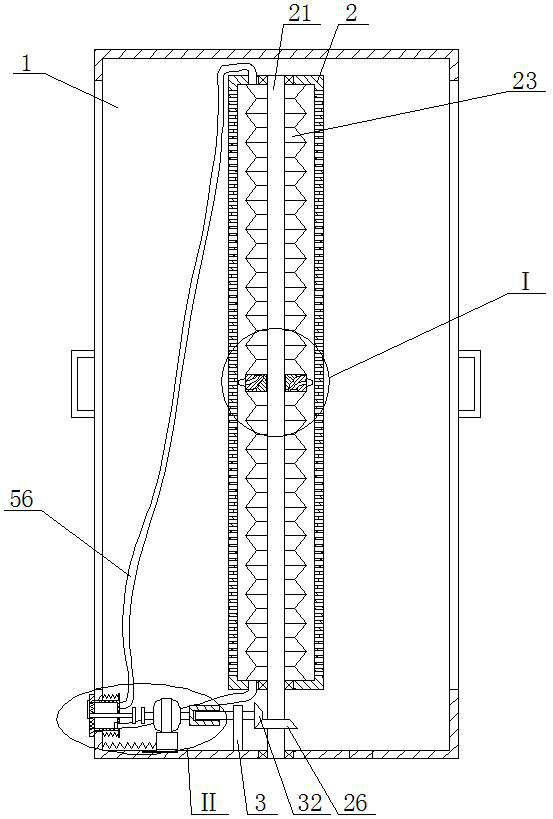
[0013]An electronically controllable cooling box for electronic information and communication equipment, as shown in the figure, includes a cabinet body 1, and the openings on both sides of the cabinet body 1 are respectively fitted with cabinet doors, and a certain gap must be left when the cabinet door is installed to facilitate the gas Exhaust,...


PUM


Abstract

An electronic information communication equipment heat dissipation box capable of being electrically controlled comprises a cabinet body, cabinet doors are installed at openings in the two sides of the cabinet body in a matched mode respectively, a certain gap needs to be reserved during installation of the cabinet doors so that gas can be exhausted conveniently, a closed box body is arranged in the cabinet body, and the front side and the rear side of the box body are fixedly connected with the corresponding inner walls of the cabinet body respectively, wherein one air inlet pipe is communicated with the inner cavity of the rear side barrel body and the inner cavity of the upper side air bag, the other air inlet pipe is communicated with the inner cavity of the front side barrel body and the inner cavity of the lower side air bag, and one-way valves are also arranged on the air inlet pipes. According to the invention, a method of blowing air from inside to outside for cooling is adopted to effectively solve the problem that communication equipment such as a terminal interface is difficult to cool due to the fact that cables are fully inserted outside, the design of the filter screen plate is adopted to effectively prevent external dust from entering the cabinet body, and automatic cleaning can be carried out after the filter screen plate is blocked, so the heat dissipation box ensures normal operation of important communication equipment; the box is suitable for being popularized and applied as a heat dissipation box of electronic information communication equipment.

Description

technical field [0001] The invention belongs to the field of maintenance of electronic information communication equipment, in particular to an electronically controllable cooling box for electronic information communication equipment. Background technique [0002] Most of the electronic information and communication equipment are installed in special heat dissipation boxes. In order to increase the space utilization, most of these heat dissipation boxes have doors on both sides. There are perforated plates for fixing communication equipment in the boxes. Both sides are filled with terminal blocks and various equipments. These equipments will generate a lot of heat when they work. Most of the existing technologies install fans on the side walls of the box for air cooling and heat dissipation. However, the inside of the box is often densely packed with communication It is difficult for the communication equipment covered by the cable to exchange heat with the outside air, and...

Claims


Application Information

Patent Timeline
IPC IPC(8): H05K7/20B01D46/10
CPCB01D46/10H05K7/20136H05K7/20181
Inventor 任加维
Owner XIANYANG VOCATIONAL TECHN COLLEGE
Why Eureka
Try Eureka