Insulating layer coating device for wires and cables

A coating device, wire and cable technology, applied in the direction of conductor/cable insulation, conductor/cable supply device, cable/conductor manufacturing, etc., can solve the problem that the insulating cloth cannot be evenly wound, the insulating cloth is inconvenient to replace, and the covering efficiency is affected and other problems, to achieve better coating effect, convenient coating, and avoid the effect of being worn

Inactive Publication Date: 2020-04-10
桐庐瑶琳永明电线电缆厂
View PDF1 Cites 4 Cited by
  • Summary
  • Abstract
  • Description
  • Claims
  • Application Information

AI Technical Summary

Problems solved by technology

A new type of wire and cable covering device in the above-mentioned patent has certain shortcomings: during use, the insulating cloth cannot be evenly wound on the cable, resulting in poor insulation effect, and the insulating cloth on the covering roller is inconvenient to replace, which greatly affects Therefore, it is urgent to design a kind of wire and cable insulating layer coating device to solve the above problems

Method used


Image

  • Insulating layer coating device for wires and cables
  • Insulating layer coating device for wires and cables
  • Insulating layer coating device for wires and cables

Examples


Embodiment 1

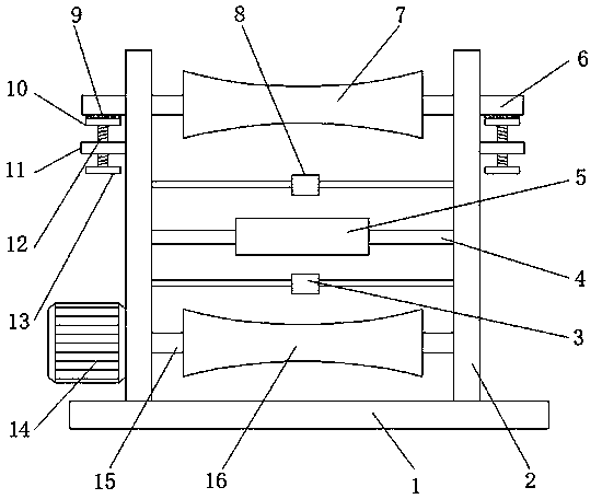
[0029] refer to Figure 1-4 , an insulating layer coating device for wires and cables, comprising a base plate 1, a vertical plate 2 is welded on the top outer wall of the bottom plate 1 near both sides, and a motor 14 is connected to the outer wall of one side of the vertical plate 2 through bolts, and the motor 14 One end of the output shaft is provided with a rotating shaft 15, and the outer wall of the rotating shaft 15 is provided with a winding roller 16, and one side outer wall of the vertical plate 2 has a mounting hole, and the inwall of the mounting hole is connected with a rotating rod 6 through a bearing rotation, and the rotating rod 6 The outer wall is provided with a pay-off roller 7, and the outer wall of one side of the vertical plate 2 is welded with a connecting rod 4, and the outer wall of one end of the connecting rod 4 is connected with an electric slide rail 5 through a bolt, and the inner wall of the electric slide rail 5 is slidably connected with a sli...

Embodiment 2

[0033] refer to Figure 5 , an insulating layer coating device for wires and cables. Compared with Embodiment 1, this embodiment also includes that the four corners of the bottom outer wall of the bottom plate 1 are welded with supporting legs, and the bottom outer walls of the supporting legs are connected by bolts. 22 to the wheel.

[0034] Working principle: when in use, the universal wheel 22 located at the bottom of the bottom plate 1 facilitates the movement of the device and makes the use more flexible.


PUM


Abstract

The invention discloses an insulating layer coating device for wires and cables. The insulating layer coating device comprises a bottom plate, and vertical plates are welded to the positions, close tothe two sides, of the outer wall of the top of the bottom plate. The outer wall of one side of each vertical plate is connected with a motor through a bolt; a rotating shaft is arranged at one end ofan output shaft of the motor, and a winding roller is arranged on the outer wall of the rotating shaft; and a mounting hole is formed in the outer wall of one side of each vertical plate, a rotatingrod is rotatably connected to the inner wall of the mounting hole through a bearing, a pay-off roller is arranged on the outer wall of the rotating rod, a connecting rod is welded to the outer wall ofone side of the vertical plate, an electric sliding rail is connected to the outer wall of one end of the connecting rod through a bolt, and a sliding block is slidably connected to the inner wall. According to the invention, the insulating cloth on the coating roller can be uniformly wound on the cable, and the sliding plate can be directly taken down from the sliding block, so that the insulating cloth on the coating roller can be conveniently and quickly fed, the use effect is better, and the cable led out by the pay-off roller can be kept tight, and the coating effect is better.

Description

technical field [0001] The invention relates to the technical field of wire and cable coating, in particular to an insulating layer coating device for wires and cables. Background technique [0002] Wires and cables are used to transmit electric energy, information and wire products that realize electromagnetic energy conversion. In a broad sense, wires and cables are also referred to as cables. In a narrow sense, cables refer to insulated cables. It can be defined as: a collection composed of the following parts; one or A plurality of insulated wire cores, and their respective possible coatings, total protective layers and outer sheaths, cables may also have additional uninsulated conductors, used to transmit electrical energy, information and wire products that realize electromagnetic energy conversion, Wires and cables are usually made by three processes: drawing, twisting and covering. [0003] After searching, the Chinese patent publication number is CN207867970U, whic...

Claims


Application Information

Patent Timeline
Patent Type & Authority Applications(China)
IPC IPC(8): H01B13/08H01B13/00
CPCH01B13/0003H01B13/0858H01B13/0866
Inventor 余早贵姚春
Owner 桐庐瑶琳永明电线电缆厂
Why Eureka
Try Eureka