Cable service life detection machine

A testing machine and life-span technology, applied in the direction of measuring electricity, measuring devices, measuring electrical variables, etc., can solve the problems of shortening the service life of cables, high cost, dragging cables, etc., to improve accuracy, convenient operation, and increase tensile force Effect

Pending Publication Date: 2020-12-15
NINGBO EBENALP FLUID EQUIP MFG
View PDF0 Cites 4 Cited by
  • Summary
  • Abstract
  • Description
  • Claims
  • Application Information

AI Technical Summary

Problems solved by technology

However, in the actual working environment, it is affected by factors such as oil mist, heat, radiation, machinery, etc., especially when in use, the cable is often dragged, and when the cable is erected, its own gravity acts on the cable itself , which often causes the cable to break, thereby reducing the service life of the cable
[0004] However, in the existing technology, there is a lack of testing equipment for the service life of the cable, and it is often impossible to effectively judge the service life of the cable in the early stage. Once the cable fails during use, the normal transmission of power will be interrupted, causing The failure of the electrical system will cause the stagnation of industrial production, and even cause safety accidents in severe cases. Therefore, a large amount of manpower and financial resources are needed for detection and repair, which is costly and inefficient.

Method used


Image

  • Cable service life detection machine
  • Cable service life detection machine
  • Cable service life detection machine

Examples


Embodiment 1

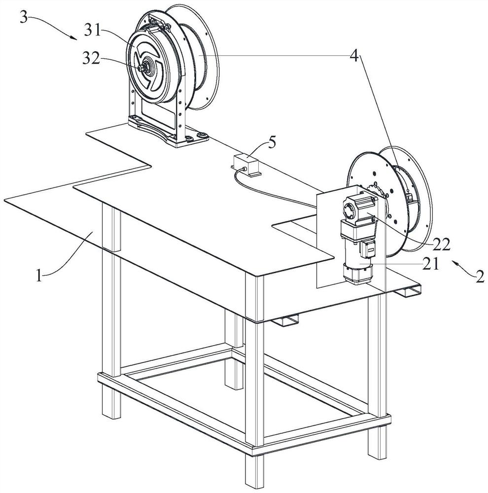
[0032] Embodiment one: refer to Figure 1-5 , a cable service life testing machine, including a frame 1, a driving part 2, a resistance part 3, two reels 4, an electronic meter 5 and two locking joints 6. Such as figure 1 As shown, the driving member 2 includes a driving motor 21 and a transmission mechanism 22, the driving motor 21 is fixed on the frame 1 by screws, the output shaft of the driving motor 21 is connected with the input end of the transmission mechanism 22, and the output end of the transmission mechanism 22 passes through The screw is installed and fixed on the axis of a wire reel 4, so that the rotation of the drive motor 21 and the transmission mechanism 22 drive the wire reel 4 to rotate, thereby realizing that the wire reel 4 is rotatably arranged on the frame 1, its structure is simple, and the motor speed controller can be used to accurately control the start and stop of the drive motor 21, as well as the forward and reverse rotation, and the operation i...

Embodiment 2

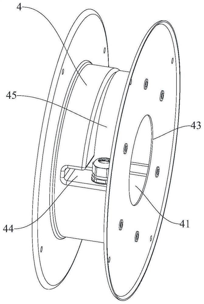
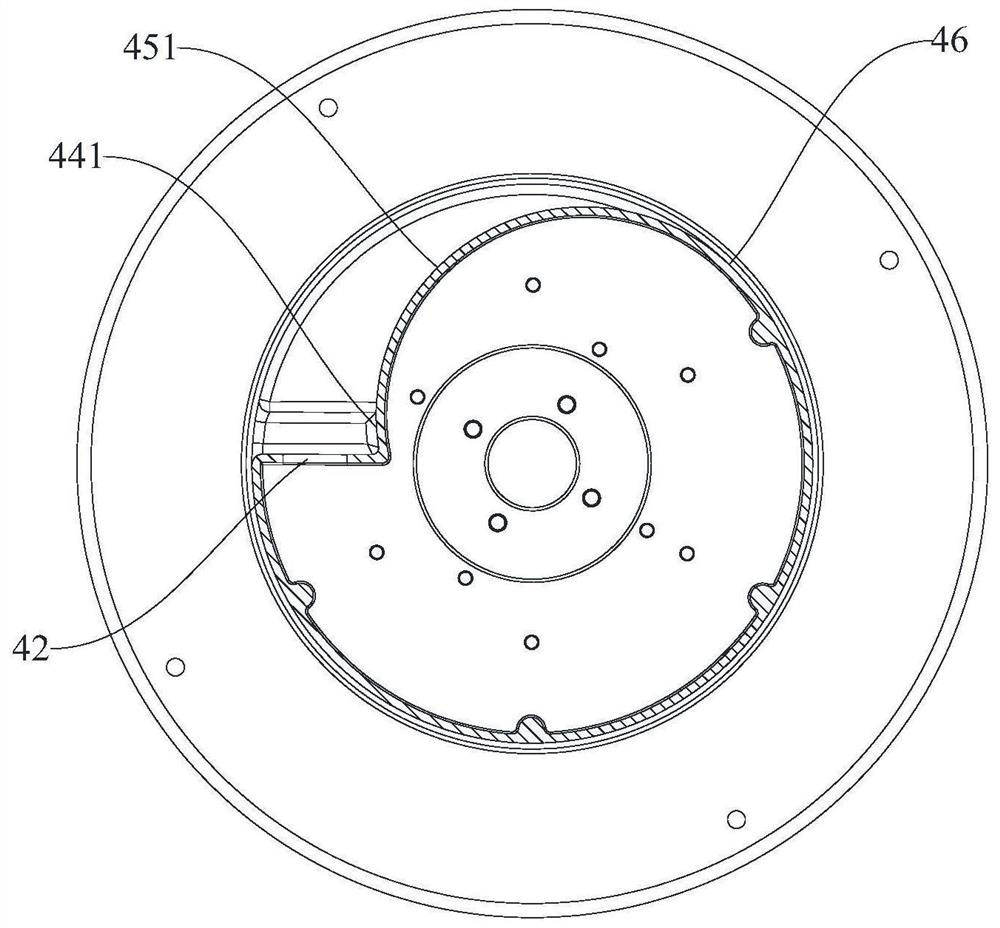
[0035] Embodiment two: refer to Figure 6-7 , implement the detection machine described in one, and also include a detection device 7, the detection device 7 includes a multimeter 71, two insulating support frames 72, two conductive columns 73 of a cylindrical structure, and two conductive sleeves 74 of an annular structure; The opening 43 is arranged on the axis of the reel 4 , and the two conductive columns 73 are respectively arranged on the axis of the two reels 4 , and one end of the two conductive columns 73 penetrates into a receiving cavity 41 through an opening 43 , respectively. The other ends of the two conductive posts 73 are respectively connected to the frame 1 through an insulating support frame 72, and the two conductive posts 73 are electrically connected to the multimeter 71; the two conductive sleeves 74 are respectively arranged in the two accommodating cavities 41 and the inner ring surfaces of the two conductive sleeves 74 are respectively rotatably arran...


PUM


Abstract

The invention discloses a cable service life detection machine, which comprises a rack, a driving piece, a resistance piece and two winding reels, and is characterized in that the two winding reels are rotatably arranged on the rack, the two winding reels are arranged in parallel, and the axes of the two winding reels are parallel to each other; the driving piece is arranged on the rack and used for driving one of the winding reels to rotate; the resistance piece is arranged on the rack and used for increasing the rotating resistance of the other winding reel. The detection machine is simple in structure, reasonable in layout, simple and convenient to operate, and capable of effectively detecting the service life of the cable.

Description

technical field [0001] The application relates to the field of cable quality inspection equipment, in particular to a cable service life detector. Background technique [0002] At present, with the gradual improvement of social automation, the electrical system is also becoming more and more complex. Cables undertake the important task of transmitting electrical energy and signals, and are widely used in various mechanical and electronic fields. Since the service life of the cable directly affects the safety of production, the safe service life of the cable is especially important in practical applications. [0003] In the existing relevant technical specifications, there is no clear requirement on the service life of the cable, and the safe service life of the cable design generally recognized in the industry is 20-30 years. However, in the actual working environment, it is affected by factors such as oil mist, heat, radiation, machinery, etc., especially when in use, the ...

Claims


Application Information

Patent Timeline
Patent Type & Authority Applications(China)
IPC IPC(8): G01N3/02G01N3/04G01N3/26G01R31/58
CPCG01N3/02G01N3/04G01N3/26G01R31/58
Inventor 吴骥余新其余新鹏
Owner NINGBO EBENALP FLUID EQUIP MFG
Why Eureka
Try Eureka