All composite material lightweight fuel tank shell for aircraft

A composite material and fuel tank technology, used in the field of aviation and aerospace vehicle components, can solve the problems of low stiffness, low performance, and heavy fuel tank weight.

Pending Publication Date: 2021-03-12
HEFEI JIANGHANG AIRCRAFT EQUIP CORP LTD
View PDF0 Cites 2 Cited by
  • Summary
  • Abstract
  • Description
  • Claims
  • Application Information

AI Technical Summary

Problems solved by technology

[0007] The purpose of the present invention is to provide a high-rigidity fuel tank for aviation aircraft. The overall structure of the fuel tank adopts the structural scheme of carbon fiber composite material skin + ring frame, which solves the problems of heavy weight, low rigidity and poor performance of the fuel tank in the prior art. Low, affecting the flight range of the aircraft and other issues

Method used


Image

  • All composite material lightweight fuel tank shell for aircraft
  • All composite material lightweight fuel tank shell for aircraft
  • All composite material lightweight fuel tank shell for aircraft

Examples


Embodiment Construction

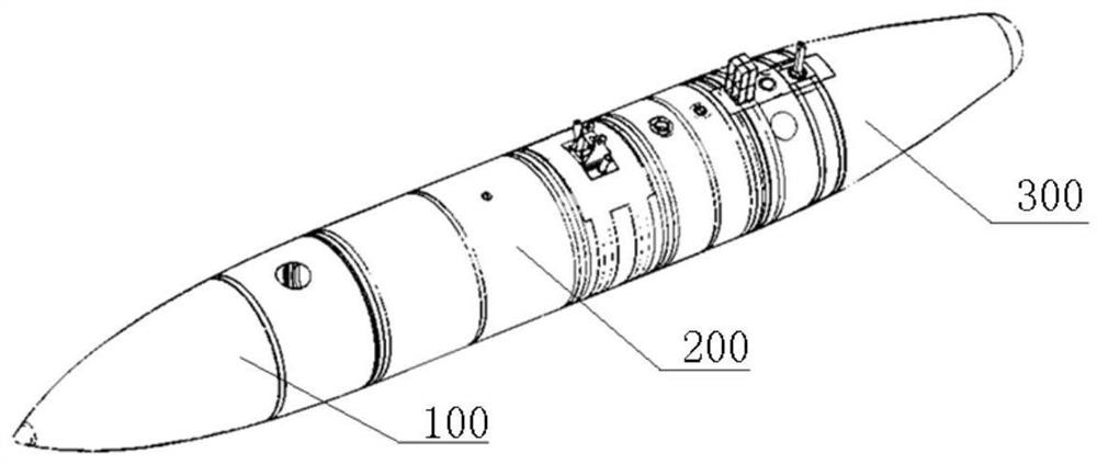
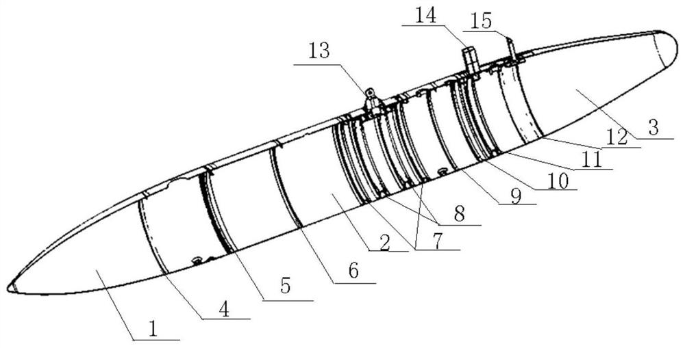
[0036] A high-rigidity composite fuel tank for aircraft, the main body is made of carbon fiber composite materials. Such as figure 1 , figure 2 , The overall structure is divided into three sections, including the front cone section 100, the middle column section 200, and the rear cone section 300. The specific structure includes cone section shell 1, column section shell 2, cone section shell 3, L-shaped Ring frame a4, L docking ring frame 5, L-shaped ring frame b6, small Ω-shaped ring frame 7, large Ω-shaped ring frame 8, L-shaped ring frame c9, L-joint ring frame b10, Ω-shaped ring frame 11, U-shaped Ring frame 12, main lifting point joint 13, stop block 14, rear hanging point joint 15, concentrated force decomposition structure 16, I-beam decomposition joint 17 and other detailed structures.

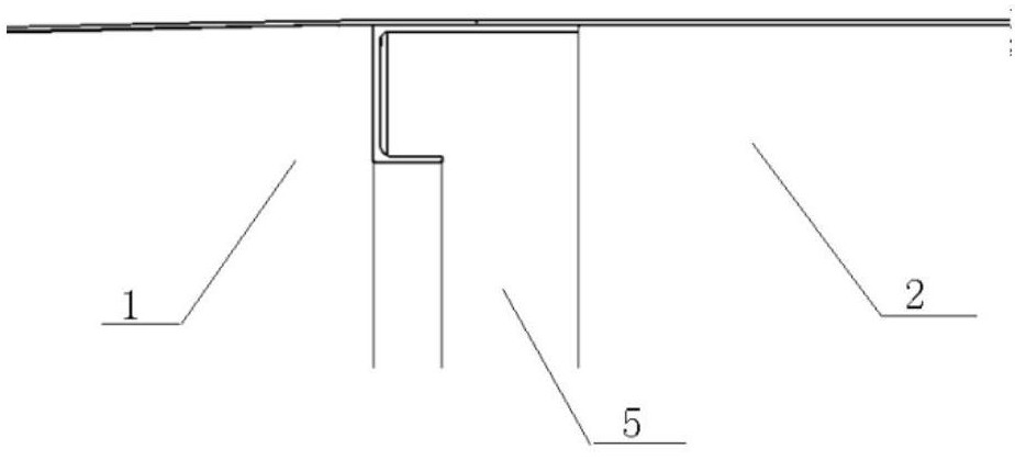
[0037] Such as image 3 , the front cone section 100 and the middle column section 200 are connected by plugging through the L docking ring frame a5. In specific use, after being...


PUM


Abstract

The invention relates to the technical field of components of aviation and aerospace crafts, and particularly relates to an all composite material lightweight fuel tank shell for an aircraft. The whole structure is divided into three sections, namely a front conical section (100), a middle column section (200) and a rear conical section (300). The concrete structure comprises a conical section shell (1), a column section shell (2), a conical section shell (3), an L-shaped ring frame a (4), an L-shaped butt joint ring frame (5), an L-shaped ring frame b (6), a small omega-shaped ring frame (7),a large omega-shaped ring frame (8), an L-shaped ring frame c (9), an L-shaped butt joint b (10), an omega-shaped ring frame (11), a U-shaped ring frame (12), a main lifting point joint (13), a stopblock (14), a rear lifting point joint (15), a concentrated force decomposition structure (16) and an I-shaped beam decomposition joint (17). A cabin section is easy to integrally design and manufacture, high in overall rigidity, light in weight, simple in structure, capable of easily guaranteeing the sealing characteristic of the box body, high in adaptability to severe environments such as saltmist and the like.

Description

technical field [0001] The invention relates to the technical field of components of aviation and aerospace vehicles, in particular to a full-composite lightweight fuel tank shell for the aircraft. Background technique [0002] The auxiliary fuel tank refers to the fuel tank with a thick middle and streamlined ends hanging under the fuselage or wing of the spacecraft. Hanging the auxiliary fuel tank can increase the range and endurance of the aircraft, and the aircraft can throw away the auxiliary fuel tank when necessary in air combat, and enter the battle with better maneuverability. [0003] In addition to the non-disposable auxiliary fuel tank designed to match the shape of the fuselage in the early stage, the main design direction of the external fuel tank is streamlined, in order to reduce the resistance generated, and reduce the negative impact on the aircraft's mobility and stability. Impact, reduce impact on other carrying equipment or fuselage structure when separ...

Claims


Application Information

Patent Timeline
Patent Type & Authority Applications(China)
IPC IPC(8): B64D37/06B64D37/04
CPCB64D37/04B64D37/06
Inventor 万孝军陈朋郑玉田李益民姚志强季宝锋王志勇王非刘发杰刘含洋
Owner HEFEI JIANGHANG AIRCRAFT EQUIP CORP LTD
Why Eureka
Try Eureka