Supercharge Your Innovation With Domain-Expert AI Agents!
Deviation rectifying device for H-shaped steel production and working method thereof
What is Al technical title?
Al technical title is built by PatSnap Al team. It summarizes the technical point description of the patent document.
A technology of deviation correction device and H-shaped steel, which is applied in the field of steel deviation correction and can solve the problems of increasing the correction force and affecting the effect of steel correction
Active Publication Date: 2021-03-16
ANHUI KINGYOUNG STRUCTURAL METAL WORK
View PDF17 Cites 2 Cited by
Summary
Abstract
Description
Claims
Application Information
AI Technical Summary
This helps you quickly interpret patents by identifying the three key elements:
Problems solved by technology
Method used
Benefits of technology
Problems solved by technology
[0005] For example, the utility model patent No. CN210023325U discloses a mold steel correction device, including a support seat, a base, a correction block, and a moving block. The upper end of the support seat is fixed to the base, and several pulleys are arranged on both sides of the support seat. , the left and right sides of the support seat are slidingly connected with moving blocks through pulleys, and a No. 1 electro-hydraulic rod is installed on the front and rear sides of the upper end of the moving block. The upper end of the No. 1 electro-hydraulic rod is provided with a correction block, and the lower end of the correction block is fixed. Plate, the utility model is easy to operate, and the pressing force comes from the weight of the correction block itself and the contraction force of the No. 1 electro-hydraulic rod, which increases the correction force, and the correction block can move back and forth, which improves the correction material rate. At the same time, the utility model has The role of grinding steel, the device can have a correction effect on mold steel steel, but it is not equipped with a feeding mechanism, and there is no positioning and clamping device for the corrected workpiece, which affects the steel correction effect
Method used
Image
Click on the blue label to locate the original text in one second.
Reading with bidirectional positioning of images and text.
Examples
Embodiment Construction
[0030] The following will clearly and completely describe the technical solutions in the embodiments of the present invention with reference to the accompanying drawings in the embodiments of the present invention. Obviously, the described embodiments are only some of the embodiments of the present invention, not all of them. Based on the embodiments of the present invention, all other embodiments obtained by persons of ordinary skill in the art without creative efforts fall within the protection scope of the present invention.
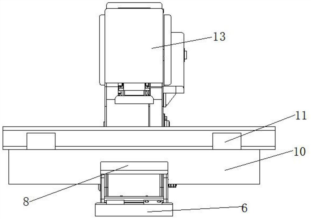
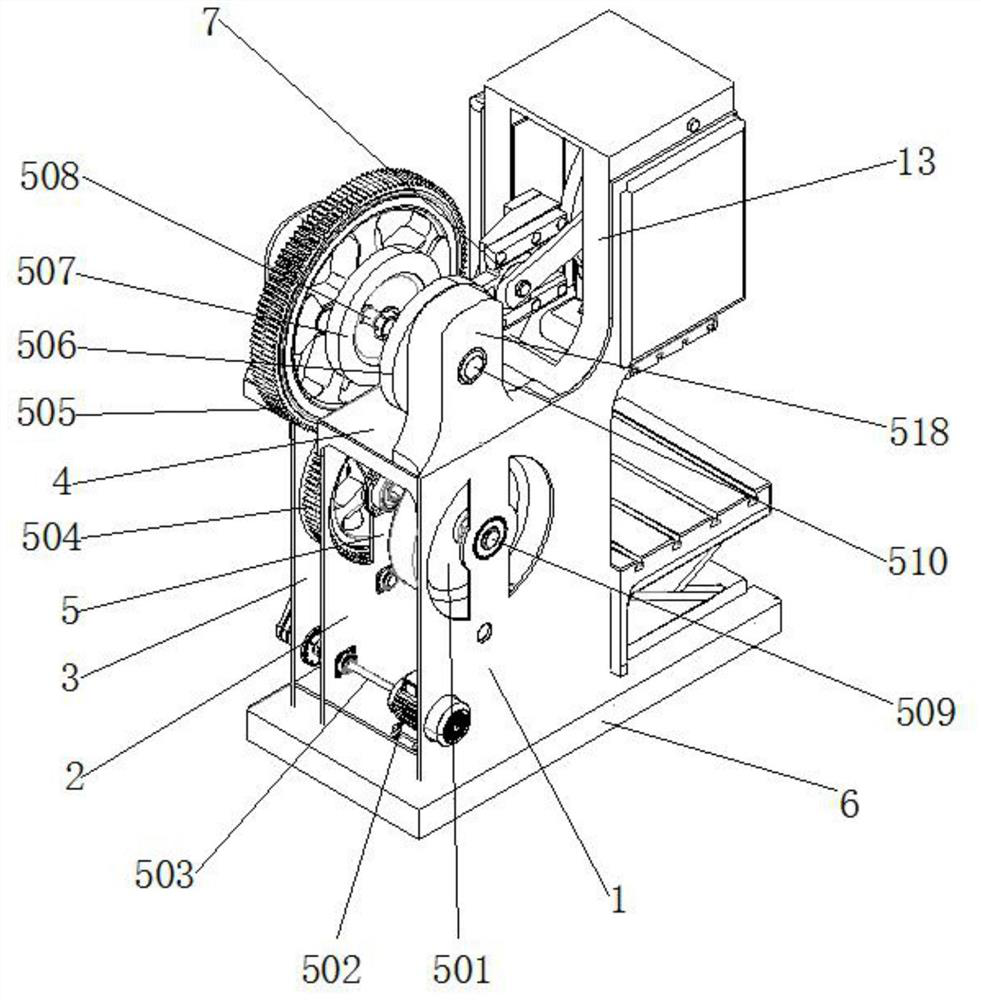
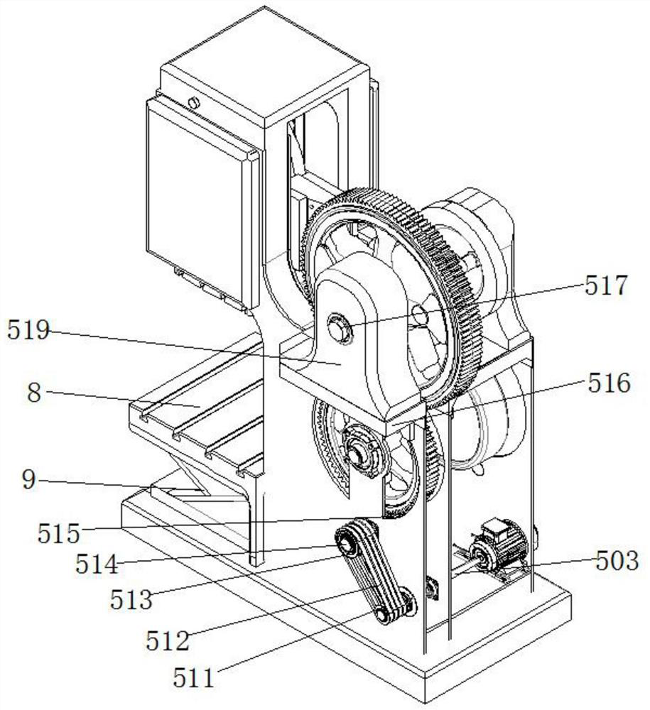
[0031] see Figure 1-7 As shown, a deviation correcting device for H-shaped steel production includes a vertical plate 1, a vertical plate 2, a vertical plate 3 3, a mounting plate 4, a transmission mechanism 5, a bottom plate 6, a reciprocating mechanism 7, a mounting platform 8, a bracket 9, Workbench 10, clamping device 11, installation groove 12, vertical board 1, vertical board 2 and vertical board 3 are fixedly connected to the top of the bottom...
PUM
Abstract
The invention discloses a deviation rectifying device for H-shaped steel production. The deviation rectifying device for H-shaped steel production comprises a vertical plate I, a vertical plate II, avertical plate III, a mounting plate, a transmission mechanism, a bottom plate, a reciprocating mechanism, a mounting table, a bracket, a worktable, a clamping device and a mounting groove, wherein the top of the bottom plate is fixedly connected with the vertical plate I, the vertical plate II and the vertical plate III, thereciprocating mechanism is fixed arranged at the position, close the topsof the vertical plate I and the vertical plate II; the transmission mechanism is fixedly installed at the position, close to the middle, in the vertical plate I, the vertical plate II and the vertical plate III, the bracket is fixedly connected to one side of the top of the bottom plate, the mounting table is fixedly connected to the top of the bracket, the mounting groove is formed in the middleof the bottom of the woktable, and the worktable is fixedly connected with the mounting table through the mounting groove; A gap is formed between a clamping block in the clamping device and the worktable, a guide block is arranged in the middle of the bottom of the clamping block, a guide groove is formed in the position, located at the bottom of the clamping block, of the top of the worktable,and the clamping block and the worktable are in sliding connection through the guide block and the guide groove.
Description
technical field [0001] The invention relates to the technical field of steel deviation correction, in particular to a deviation correction device for H-shaped steel production and a working method thereof. Background technique [0002] Shaped steel refers to straight steel with a certain cross-sectional shape and a relatively large ratio of length to section circumference. H-shaped steel is a type of shaped steel, in which H-shaped steel includes upper flange, lower flange, and The web between them is a steel structure dominated by H-shaped steel. Because of its scientific and reasonable structure, good plasticity and flexibility, and high structural stability, it is suitable for building structures that withstand large vibration and impact loads, and has strong resistance to natural disasters. It is mostly used in load-bearing positions of various buildings or steel structure houses. [0003] In the production of H-shaped steel, due to the uneven condition of the hand, the...
Claims
Application Information
Patent Timeline
Application Date:The date an application was filed.
Publication Date:The date a patent or application was officially published.
First Publication Date:The earliest publication date of a patent with the same application number.
Issue Date:Publication date of the patent grant document.
PCT Entry Date:The Entry date of PCT National Phase.
Estimated Expiry Date:The statutory expiry date of a patent right according to the Patent Law, and it is the longest term of protection that the patent right can achieve without the termination of the patent right due to other reasons(Term extension factor has been taken into account ).
Invalid Date:Actual expiry date is based on effective date or publication date of legal transaction data of invalid patent.
