Automatic feeding and discharging mechanism for general electrical equipment production

An automatic loading and unloading, general electric technology, used in metal processing equipment, feeding devices, forming tools, etc., can solve the problem of unsolved vacuum suction cup aging and need to be replaced, to extend service life and practicability, improve stability, Guarantee the effect of grabbing effect

Inactive Publication Date: 2021-03-16
WUJIANG CITY XUSHI ELECTROMECHANICAL CO LTD
View PDF1 Cites 0 Cited by
  • Summary
  • Abstract
  • Description
  • Claims
  • Application Information

AI Technical Summary

Problems solved by technology

[0003] For example, an automatic loading and unloading mechanism disclosed in the invention with the authorized notification number CN207996948U, although it improves the ability to remove the dust on the surface of the material when grabbing the material, it does not solve the problem that the vacuum suction cup needs to be replaced due to aging under long-term use. problem, for which we propose an automatic loading and unloading mechanism produced by general electric equipment

Method used


Image

  • Automatic feeding and discharging mechanism for general electrical equipment production
  • Automatic feeding and discharging mechanism for general electrical equipment production
  • Automatic feeding and discharging mechanism for general electrical equipment production

Examples


Embodiment Construction

[0022] In order to make the technical means, creative features, goals and effects achieved by the present invention easy to understand, the present invention will be further elaborated below in conjunction with specific embodiments, but the following embodiments are only preferred embodiments of the present invention, not all. Based on the examples in the implementation manners, other examples obtained by those skilled in the art without making creative efforts all belong to the protection scope of the present invention. The experimental methods in the following examples, unless otherwise specified, are conventional methods, and the materials, reagents, etc. used in the following examples, unless otherwise specified, can be obtained from commercial sources.

[0023] Example:

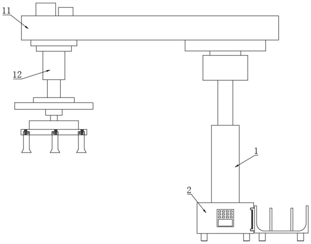
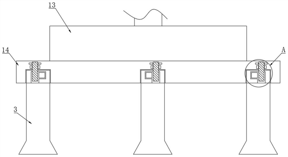
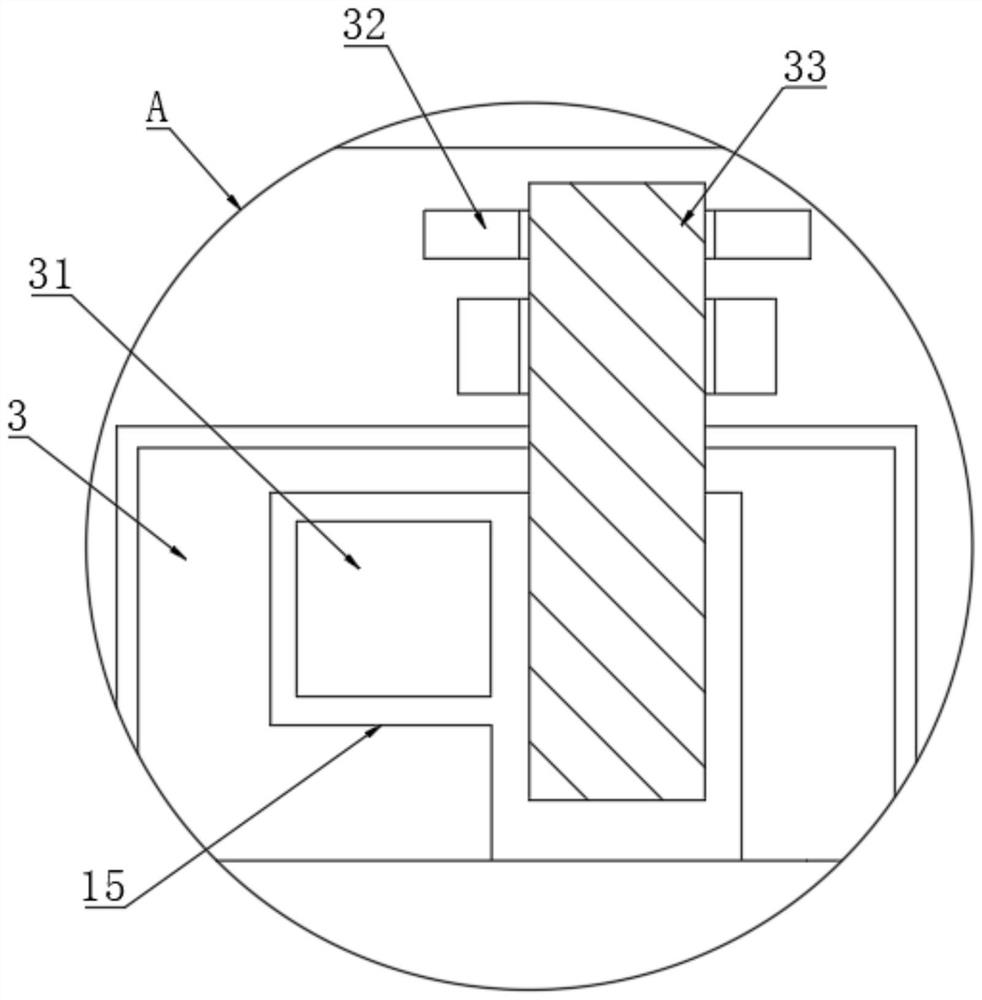
[0024] like Figure 1-Figure 3 As shown, an automatic loading and unloading mechanism produced by general electric equipment includes a first cylinder 1, a support 11 is provided on the top surface of t...


PUM


Abstract

The invention discloses an automatic feeding and discharging mechanism for general electrical equipment production. The automatic feeding and discharging mechanism comprises a first air cylinder, wherein a support is arranged on the surface of the top end of the first air cylinder, a second air cylinder is arranged on the surface of the bottom end of the support, a fan chamber is arranged on the surface of the bottom end of the second air cylinder, and a detaching mechanism is arranged on the surface of the bottom end of the fan chamber; the detaching mechanism comprises a grabbing frame, thegrabbing frame is located on the surface of the bottom end of the fan chamber, L-shaped empty grooves are formed in the surface of one side of the grabbing frame, a fixing block is movably connected to the inner side of each L-shaped empty groove, a vacuum suction cup is fixedly connected to the surface of one end of each fixing block, and one ends of the vacuum suction cups are located at the inner side of the grabbing frame; and the other ends of the vacuum suction cups are located at the outer side of the grabbing frame, plug pin plates are fixedly connected to the surface of one side of the grabbing frame, and an inserting rod is connected into each plug pin plate in a penetrating manner. Through the arranged detaching mechanism, after the device is used for a long time, when the vacuum suction cups are aged and cannot continue to play the original effect, replacement can be conducted.

Description

technical field [0001] The invention relates to the technical field of electrical equipment production, in particular to an automatic loading and unloading mechanism for general electrical equipment production. Background technique [0002] Metal stamping is a process that uses punches and molds to deform or break stainless steel, iron, aluminum, copper and other plates and heterogeneous materials to achieve a certain shape and size. In the process of metal stamping, in order to better realize mechanical For automation, it is necessary to design a loading and unloading mechanism for hardware stamping automation; [0003] For example, an automatic loading and unloading mechanism disclosed in an invention with the authorized notification number CN207996948U, although it improves the ability to remove the dust on the surface of the material when grabbing the material, it does not solve the problem that the vacuum suction cup needs to be replaced due to aging under long-term use...

Claims


Application Information

Patent Timeline
Patent Type & Authority Applications(China)
IPC IPC(8): B21D43/18B21D37/00
CPCB21D43/18B21D37/00
Inventor 徐棉荣
Owner WUJIANG CITY XUSHI ELECTROMECHANICAL CO LTD
Why Eureka
Try Eureka