

Hardware pin jitter test system, method and device
A testing method and testing device technology, applied in the direction of electrical connection testing, etc., can solve the problems of undetectable hardware influence of pin pins, difficult pin pin testing, etc., and achieve the effect of convenient and fast testing
- Summary
- Abstract
- Description
- Claims
- Application Information
AI Technical Summary
Problems solved by technology
Method used
Image

Examples
Embodiment 1
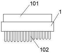
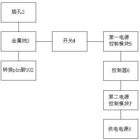
[0034] Such as figure 1 and 2 As shown, this embodiment provides a hardware pin jitter test system, including an adapter board 1 , a first power control module 4 , a second power control module 6 , and a controller 5 .
[0035] During the test, the pins of the hardware are plugged into the device to be plugged (such as a server) through the adapter board 1 , and the controller 5 controls the vibration of the hardware pins through the adapter board 1 .
[0036] Specifically, the adapter board 1 is provided with a slot 101 and an adapter pin 102. The adapter pin 102 corresponds to the hardware pin one-to-one and has the same structure, so as to be inserted into the device to be inserted. There is a jack 103 for inserting the hardware pin. When in use, the hardware pin is inserted into the slot 101, and then when the transfer pin 102 is inserted into the device to be inserted, the hardware pin is connected to the device to be inserted through the adapter board 1 Connection. Th...
Embodiment 2
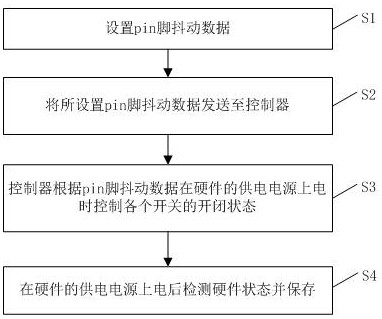
[0040] Such as image 3 As shown, based on the system of Embodiment 1, a hardware pin jitter testing method of the system of this embodiment comprises the following steps:
[0041] S1, set pin shake data;
[0042] The set pin jitter data includes the power-on delay time of each pin of the hardware, the jitter frequency and the jitter duration during power-on.
[0043] It should be noted that the tester sets the jitter data of each pin according to the test needs, and can set any jitter data to detect the impact of different jitters on the hardware.
[0044] In addition, the hardware pins can be grouped according to certain rules, and the pin jitter data can be set for each group. For example, the long and short needles of the pins, the long needle first contacts the device to be inserted, and the short needle then contacts the device to be inserted, and the pins are grouped according to the length and short needle.
[0045] S2, sending the set pin jitter data to the control...
Embodiment 3
[0053] Such as Figure 4 As shown, based on the system of Embodiment 1, the system of this embodiment is a hardware pin jitter testing device, which includes the following functional modules.
[0054] (1) Jitter data setting module 101: set the pin shake data;
[0055] The set pin jitter data includes the power-on delay time of each pin of the hardware, the jitter frequency and the jitter duration during power-on.
[0056] It should be noted that the tester sets the jitter data of each pin according to the test needs, and can set any jitter data to detect the impact of different jitters on the hardware.
[0057]In addition, the hardware pins can be grouped according to certain rules, and the pin jitter data can be set for each group. For example, the long and short needles of the pins, the long needle first contacts the device to be inserted, and the short needle then contacts the device to be inserted, and the pins are grouped according to the length and short needle.
[0...
PUM
 Abstract
Description
Claims
Application Information