Drainage bottle for cardiovascular medicine and using method thereof

A drainage bottle and cardiovascular technology, which is applied in the field of medical devices, can solve the problems of fixing drainage bottles for cardiovascular medicine, low safety of drainage bottles, and inability to alert the excessive amount of drainage fluid, so as to ensure accuracy and improve safety. , to avoid the effect of false positives

Pending Publication Date: 2021-03-26
庞娟莹
View PDF0 Cites 0 Cited by
  • Summary
  • Abstract
  • Description
  • Claims
  • Application Information

AI Technical Summary

Problems solved by technology

[0003] The existing drainage bottles for cardiovascular medicine usually need to be fixed between the outside or placed on the ground during use, which cannot effectively fix the drainage bottles for cardiovascular medicine, and cannot be used for cardiovascular medicine according to actual needs. There are multiple fixing methods for hanging or placing the drainage bottle, and when the suspension is used, it is impossible to alarm the excessive amount of drainage fluid inside the box, resulting in low safety of the drainage bottle used in cardiovascular medicine, and the scope of use is limited. As a result, the work efficiency of the drainage bottle for cardiovascular medicine is low, and the service life is short. For this reason, we propose a drainage bottle for cardiovascular medicine

Method used


Image

  • Drainage bottle for cardiovascular medicine and using method thereof
  • Drainage bottle for cardiovascular medicine and using method thereof
  • Drainage bottle for cardiovascular medicine and using method thereof

Examples


Embodiment Construction

[0027] The preferred embodiments of the present invention will be described below in conjunction with the accompanying drawings. It should be understood that the preferred embodiments described here are only used to illustrate and explain the present invention, and are not intended to limit the present invention.

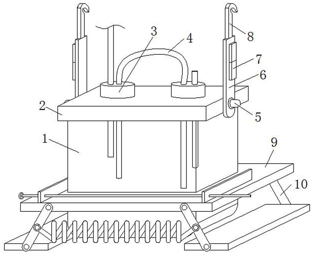
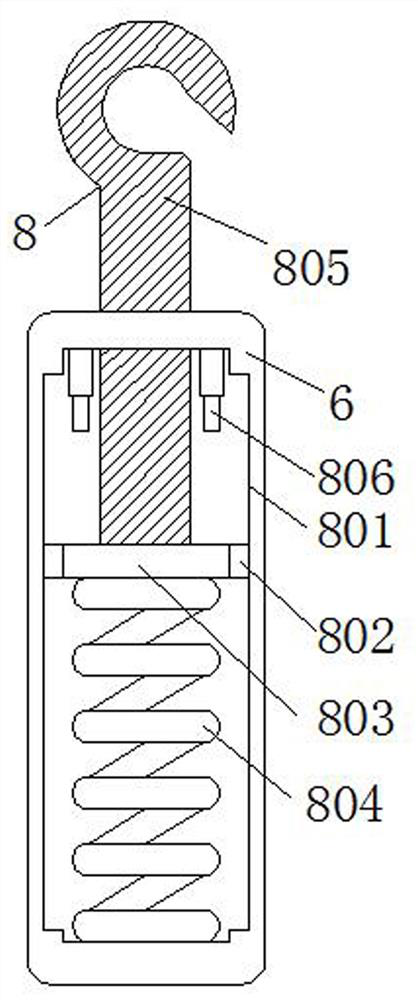
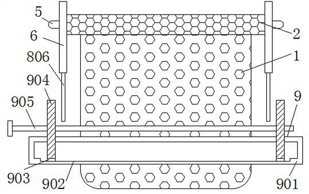
[0028] Such as Figure 1-Figure 5 As shown, a drainage bottle for cardiovascular medicine includes a box body 1, a cover plate 2, a connecting plug 3, a drainage tube 4, a rotating shaft 5, a connecting plate 6, a warning light 7, a suspension alarm mechanism 8, and a first chute 801, the first slider 802, the movable plate 803, the first return spring 804, the hanging plate 805, the push switch 806, the clamping mechanism 9, the fixed plate 901, the second chute 902, the second slider 903, the splint 904, Two-way screw rod 905, bottom support turning mechanism 10, first movable shaft 1001, support plate 1002, second movable shaft 1003, bottom plate 1004, fixed shaf...


PUM


Abstract

The invention relates to a drainage bottle for cardiovascular medicine. The drainage bottle comprises a box body, a cover plate is installed at the top of the box body, a connecting plug is connectedto the top of the cover plate, a drainage tube is inserted into the connecting plug, and a rotating shaft is installed on the outer side of the cover plate. By arranging a suspension alarm mechanism,a connecting plate is rotated through the rotating shaft, so that the connecting plate is kept at the top of the outer side of the box body, the box body is suspended on one side of a sickbed of a patient through a suspension plate, the fixing effect of the box body is ensured, and the drainage tube drains fluid at an affected part of the patient, so that drainage fluid is stored in the box body,under the action of gravity, the connecting plate moves downwards along with the weight of the box body, the suspension plate moves upwards through a movable plate, a first sliding groove and a firstsliding block, the movable plate extrudes a pressing switch, under the electric connection action of the pressing switch and a warning lamp, medical staff are warned when the drainage fluid in the boxbody is stored to a certain position, and the medical staff can conveniently drain the fluid in time.

Description

technical field [0001] The invention relates to a drainage bottle for cardiovascular medicine, which belongs to the technical field of medical devices. Background technique [0002] The Department of Cardiology, that is, the Department of Cardiovascular Medicine, is a clinical department set up by the major internal medicine departments of hospitals at all levels for the diagnosis and treatment of cardiovascular and vascular diseases. The diseases treated include angina pectoris, hypertension, sudden death, arrhythmia, heart failure, premature beats, arrhythmia, Myocardial infarction, cardiomyopathy, myocarditis, acute myocardial infarction and other cardiovascular diseases. [0003] The existing drainage bottles for cardiovascular medicine usually need to be fixed between the outside or placed on the ground during use, which cannot effectively fix the drainage bottles for cardiovascular medicine, and cannot be used for cardiovascular medicine according to actual needs. The...

Claims


Application Information

Patent Timeline
IPC IPC(8): A61M1/00A61G7/05
CPCA61G7/0503A61M2205/18A61M2205/3382A61M2209/08
Inventor 庞娟莹郭燕
Owner 庞娟莹
Why Eureka
Try Eureka