
Guide roller, steel belt guide mechanism and material receiving system

A technology of guiding rollers and guiding mechanisms, applied in thin material handling, coiling strips, transportation and packaging, etc., can solve the problems of uneven collection of steel belts, easy collapse of narrow belts, etc. Untidy, solve the effect of uneven trimming and receiving

Active Publication Date: 2021-03-26
BICHAMP CUTTING TECH (HUNAN) CO LTD
View PDF7 Cites 0 Cited by
  • Summary
  • Abstract
  • Description
  • Claims
  • Application Information

AI Technical Summary

Problems solved by technology

[0013]The object of the present invention is to provide a guide roller, a steel belt guiding mechanism and a material receiving system, to solve the problem of irregular steel belt receiving, and to solve the problem that the narrow belt is easy to collapse , and at the same time improve the precision of adjusting the steel belt guide and improve the service life of the guide
[0015]In the above scheme, the adjustable rotating sleeve can realize the gap adjustment between the guide cavities, so as to be suitable for steel strips of different widths and sizes, and can realize the guiding effect well. Solve the problem of uneven receiving of steel strips, solve the problem of narrow strips that are easy to collapse, increase the wear resistance of guide rollers, improve the guiding accuracy of guide rollers and increase their service life

Method used


Image

  • Guide roller, steel belt guide mechanism and material receiving system
  • Guide roller, steel belt guide mechanism and material receiving system
  • Guide roller, steel belt guide mechanism and material receiving system

Examples


Embodiment Construction

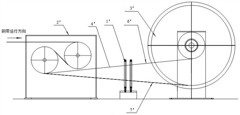
[0042] The present invention will be described in detail below with reference to the accompanying drawings and examples. It should be noted that, in the case of no conflict, the embodiments of the present invention and the features in the embodiments can be combined with each other. For the convenience of description, if the words "up", "down", "left" and "right" appear in the following, it only means that the directions of up, down, left and right are consistent with the drawings themselves, and do not limit the structure.

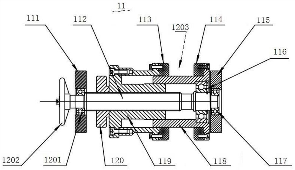
[0043] Such as image 3 As shown, a guide roller 11 provided in this embodiment includes a first bearing support 111, a screw 112, a first retaining ring 113, a second retaining ring 114, a second bearing support 115, a third bearing 116, a second Bearing 117, positioning sleeve 118, adjustable sleeve 119, lock nut 120, first bearing 1201 and hand wheel 1202.

[0044]Both ends of the screw 112 are respectively provided with a first bearing support 111 a...


PUM


Abstract

The invention provides a guide roller, a steel belt guide mechanism and a material receiving system. The guide roller comprises a screw, an adjustable sleeve and a positioning sleeve, wherein a firstbearing support and a second bearing support are arranged at two ends of the screw respectively, an external thread section is arranged on the screw and is close to the first bearing support, the adjustable sleeve is in threaded connection with the external thread section, one end of the positioning sleeve is installed on the screw through a third bearing, and the other end of the positioning sleeve is connected with the corresponding end of the adjustable sleeve in a sleeved mode; a guide cavity is formed between the positioning sleeve and the adjustable sleeve; and a first check ring is arranged on the vertical side wall, forming the guide cavity, of the adjustable sleeve, and a second check ring is arranged on the vertical side wall, forming the guide cavity, of the positioning sleeve.Compared with the prior art, the guide roller solves the problem that edge cutting and material receiving are not orderly, guarantees that material receiving is smooth, guarantees that narrow-belt material receiving is safe and reliable, avoids the phenomenon of material collapse, and meanwhile greatly prolongs the service life of the guide mechanism.

Description

technical field [0001] The invention relates to the technical field of bimetal band saw blade processing, in particular to a guide roller, a steel belt guide mechanism and a material receiving system. Background technique [0002] Bimetallic band saw blade products are widely used in the field of sawing metal materials. The tooth material is made of high-speed steel, and the back material is made of spring steel. Through laser welding or electron beam welding, the high-speed steel wire and the spring steel strip are firmly welded together. The resulting product is called a composite steel strip. The composite steel strip is cold-processed by milling to form sawtooth, and then processed by tooth division and heat treatment to become a bimetallic band saw blade product. [0003] In order to control the width of the composite steel strip, before the spring steel strip is welded, it is necessary to trim the incoming material, one is to strictly control the width, and the other ...

Claims


Application Information

Patent Timeline
Patent Type & Authority Applications(China)
IPC IPC(8): B65H27/00B65H23/26B65H18/08
CPCB65H27/00B65H23/26B65H18/08Y02P70/10
Inventor 成有才
Owner BICHAMP CUTTING TECH (HUNAN) CO LTD
Learn More