Supercharge Your Innovation With Domain-Expert AI Agents!

Method and device for shaping an inductance coil

A technology of winding components and equipment, applied in the direction of electrical components, electric components, electromechanical devices, etc., can solve the problems of difficult manufacturing and high cost of winding components

Pending Publication Date: 2021-03-26
GEHRING E TECH GMBH
View PDF2 Cites 0 Cited by
  • Summary
  • Abstract
  • Description
  • Claims
  • Application Information

AI Technical Summary

Problems solved by technology

However, the problem is that the cost of building such a bending station is relatively high
Furthermore, conductor pieces can often only be reformed into identical or slightly different winding elements by means of bending stations
This makes the advantageous manufacture of winding elements more difficult, especially in the case of high shape diversity and few identical winding elements

Method used


Image

  • Method and device for shaping an inductance coil
  • Method and device for shaping an inductance coil
  • Method and device for shaping an inductance coil

Examples


Embodiment Construction

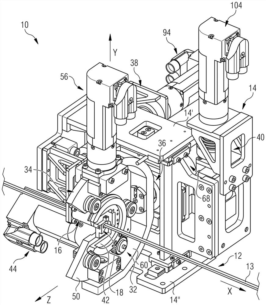
[0055] figure 1A device 10 is shown for forming, for example, a hair-fork-shaped winding element (“hairpin”) from a conductor 12 . The conductor 12 extends elongately in the longitudinal direction (X direction) and has an outer side 13 extending in the longitudinal direction. The components of the apparatus 10 are coupled or fastened to a frame 14 which serves as a support structure.

[0056] Device 10 includes ( figure 1 Partially hidden in the center) guide 16 and retrofit device 18 through which the conductor 12 is guided. The reforming device 18 is movable relative to the guide 16 by means of pivoting devices and compensating devices, so that the conductor 12 guided by the guide 16 and the reforming device 18 can be reformed, for example, into a fork-shaped winding element. This is explained in detail below, where, with reference to figure 1 The spatial axes (X, Y, and Z) drawn in . The X-axis extends along the longitudinal direction of the conductor 12, and the Y-axi...


PUM


Abstract

The invention relates to a method and a device (10) for shaping a preferably hairpin-type inductance coil from a conductor (12).

Description

technical field [0001] The invention relates to a method for forming a winding element having the features of the preamble of claim 1 . Furthermore, the invention relates to a device for forming winding elements having the features of the preambles of the co-claims. Finally, the invention relates to the use of such an apparatus for forming winding elements with the features of the further co-claims. Background technique [0002] Methods and devices of the type mentioned at the outset are known to the applicant from practice. Therefore, in the production of electric motors for traction drives, individual winding elements (insert coils, so-called “hairpins”) are produced which are processed further in a subsequent process to form the stator winding. In order to achieve a higher efficiency of the electric motor due to the higher filling degree, a transition is made from a circular conductor cross section to a rectangular conductor cross section in hairpin technology. Within ...

Claims


Application Information

Patent Timeline
Patent Type & Authority Applications(China)
IPC IPC(8): H02K15/04
CPCH02K15/0421H02K15/064
Inventor 朱塞佩·扎娜法布里齐奥·朱拉代
Owner GEHRING E TECH GMBH
Features
  • R&D
  • Intellectual Property
  • Life Sciences
  • Materials
  • Tech Scout
  • Unparalleled Data Quality
  • Higher Quality Content
  • 60% Fewer Hallucinations
Learn More