A positioning device for separated Hopkinson compression bar specimen

A Hopkinson pressure bar and positioning device technology, applied in measurement devices, analytical materials, instruments, etc., can solve problems such as errors, inconvenient positioning of specimens, and achieve the effect of accurate test data

Active Publication Date: 2022-04-12
SOUTHWEST JIAOTONG UNIV
View PDF30 Cites 0 Cited by
  • Summary
  • Abstract
  • Description
  • Claims
  • Application Information

AI Technical Summary

Problems solved by technology

[0004] The separate Hopkinson compression rod in the prior art is inconvenient to locate the specimen during use, and the experimental results may have errors due to the different axes of the incident rod and the transmission rod

Method used


Image

  • A positioning device for separated Hopkinson compression bar specimen
  • A positioning device for separated Hopkinson compression bar specimen
  • A positioning device for separated Hopkinson compression bar specimen

Examples


no. 1 example

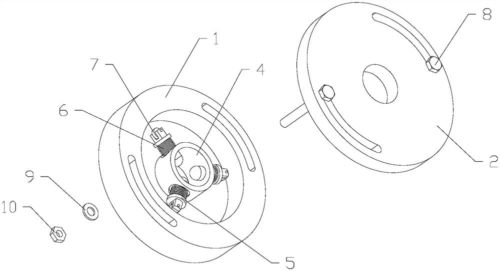
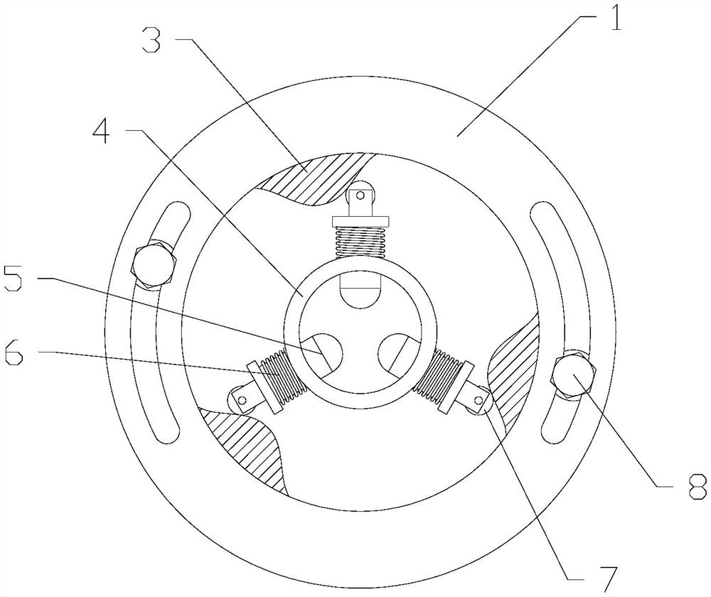
[0027] Please refer to figure 1 , the present embodiment provides a positioning device for a separate Hopkinson pressure bar test piece, which includes a carrier plate 1 equipped with a positioning element, a cam plate 2 and a connector for realizing the positioning of each size of the test piece, the carrier plate 1 and the The cam disc 2 is connected by a connecting piece, the connecting piece includes a bolt 8, a flat washer 9 and a nut 10, the positioning element includes an inner ring body 4, a driven rod 5, a spring 6 and a roller 7, the cam disc 2 in this embodiment, the bearing The material of the disk 1, the inner ring body 4 and the driven rod 5 are all aluminum alloys. There are three driven rods 5, and the three driven rods 5 are radially symmetrically distributed. The roller 7 is connected to the driven rod 5, and the spring 6 It is arranged on the driven rod 5, the driven rod 5 is connected to the inner ring body 4, and the inner side of the cam plate 2 is provid...


PUM


Abstract

The invention discloses a positioning device for a separated Hopkinson compression bar test piece, which includes a bearing plate, a cam plate and a connecting piece, the bearing plate and the cam plate are connected through the connecting piece, and the connecting piece includes a bolt, a flat washer and a nut , the positioning element is arranged in the bearing plate, the positioning element includes an inner ring body, a driven rod, a spring and a roller, the bearing plate and the cam plate are relatively rotatable, so that the roller rolls on the convex structure surface of the cam plate, and then drives the driven rod Compress the spring, and at the same time, the inner end of the driven rod moves closer to position the test piece, and then the connecting piece is loosened, and the spring restores the deformation to restore the driven rod to its original state; this device can overcome the misalignment between the test piece and the incident rod and the transmission rod The shortcomings of errors caused by the heart, so as to obtain more accurate test data.

Description

technical field [0001] The invention relates to the technical field of experimental devices, in particular to a positioning device for a split Hopkinson pressure bar test piece. Background technique [0002] The Hopkinson pressure bar technique was originally proposed by Hopkinson in 1914, when it was used to measure the pulse waveform under impact load. [0003] The split Hopkinson pressure rod is divided into two parts, one is the incident rod and the other is the transmission rod. The test piece is placed in the middle of the two rods, and the stress-strain relationship of the material is measured under the impact load. This technology was first proposed by Hopkinson in 1914, and in 1949, after the improvement of Kolsky, the prototype of the split Hopkinson pressure bar technology was able to appear. So this technique is called a split Hopkinson bar, or Kolsky bar. Later, with the joint efforts of researchers at home and abroad, this technology has become more and more...

Claims


Application Information

Patent Timeline
Patent Type & Authority Patents(China)
IPC IPC(8): G01N3/02G01N3/04
CPCG01N3/02G01N3/04
Inventor 王战江冉鹏飞秦娜
Owner SOUTHWEST JIAOTONG UNIV
Why Eureka
Try Eureka