Electric capacity level meter

A capacitive liquid level and capacitive technology, which is applied in the direction of liquid level indicators for physical variable measurement, can solve problems such as capacitance liquid level meter reading errors, and achieve the effects of overcoming errors, simple structure, and improving measurement accuracy

Inactive Publication Date: 2004-09-01
林金
View PDF0 Cites 0 Cited by
  • Summary
  • Abstract
  • Description
  • Claims
  • Application Information

AI Technical Summary

Problems solved by technology

[0002] The readings of capacitance level gauges on the market are often affected by changes in the dielectric constant of the dielectric and cause errors

Method used


Image

  • Electric capacity level meter
  • Electric capacity level meter
  • Electric capacity level meter

Examples


Embodiment Construction

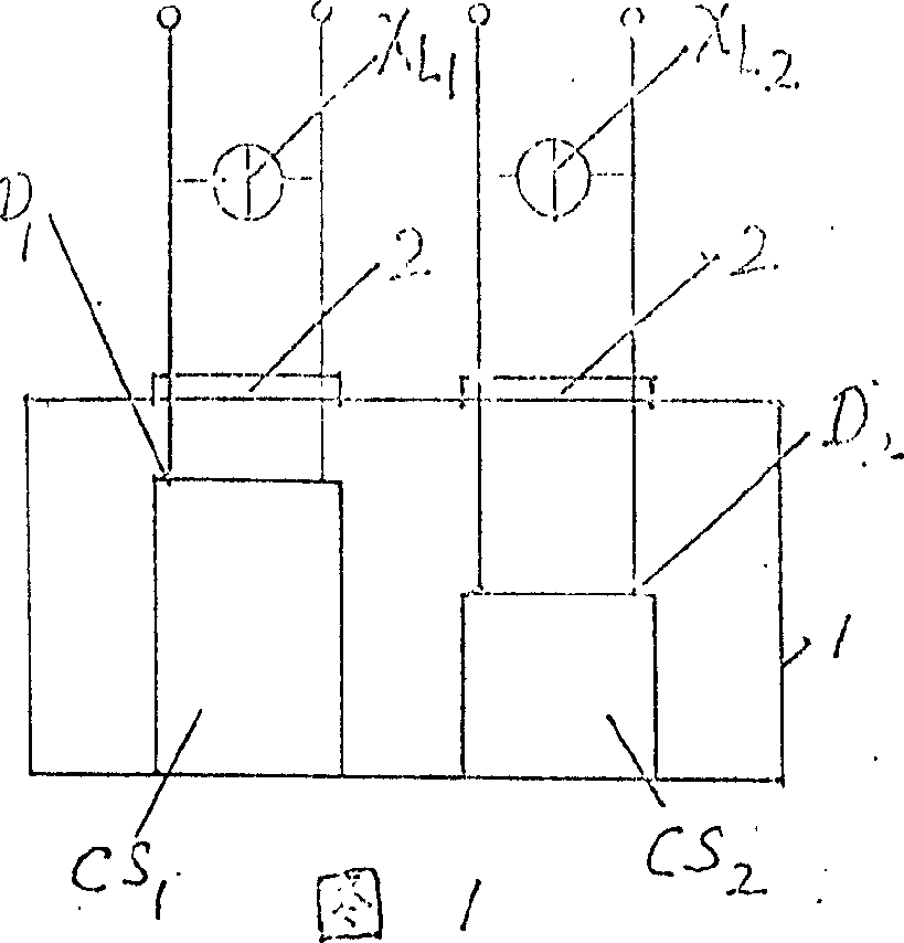
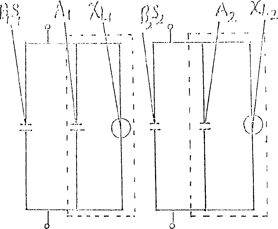
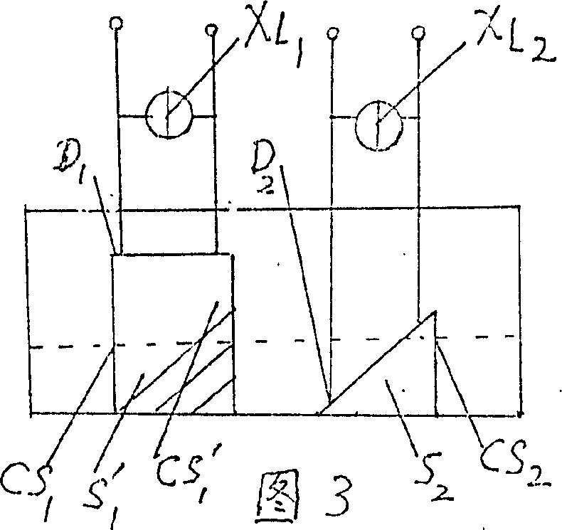
[0014] From Figure 1, figure 2 Look, this capacitor liquid level gauge is equipped with two sensors, the first capacitor Cs 1 , the second capacitance Cs 2 The lower end is located at the bottom of the container (1), the upper end is fixed by the outlet pin (2), and the first capacitor Cs 1 and the first inductive reactance X L1 Parallel connection (first inductive reactance X L1 and the first equivalent capacitance A in the first capacitor 1 resonance), forming the first sensor D 1 , the second capacitance Cs 2 and the second inductive reactance X L2 Parallel connection (the second inductive reactance X L2 and the first equivalent capacitance A in the second capacitor 2 resonance), forming the second sensor D 2 , the first capacitance Cs 1 and the second capacitor Cs 2 as the first sensor D 1 , the second sensor D 2 The electrode is immersed in the liquid. With the change of the liquid volume, part of the electrode is in the air and part is immersed in the liquid...


PUM


Abstract

The liquid level gauge includes two output capacitors of the two sensors Cs1=B1S1+A1, Cs2=B2S2+A2 where S1, S2 as the areas immersed in liquid. The equivalent capacities A1, A2 are the fixed value. Let resonant vibration happens between the inductance XL1, XL2 and the equivalent capacities A1, A2, making the current inputting to the resonance circuit equal to zero. Thus the Cs1, Cs2 only relates to B1S1, B2S2. The meter reads out the ration between the output signals of the two sensors so that the measured value is only related to the ratio between the capacitor area of S1, S2 immersed in liquid. The invented sensor is not influenced by the change of dielectric constant.

Description

(1) Technical field: [0001] The invention relates to a capacitance liquid level gauge for measuring liquid volume, especially for measuring the storage volume of gasoline in the gasoline tank of vehicles. (two) background technology: [0002] The readings of capacitance level gauges on the market are often affected by changes in the dielectric constant of the dielectric, resulting in errors. (3) Contents of the invention: [0003] The purpose of the present invention is to provide a capacitance liquid level gauge which can make the reading of the capacitance liquid level gauge irrelevant to the change of the dielectric constant of the dielectric and only related to the area of ​​the capacitor immersed in the liquid, so as to accurately measure the liquid storage volume. [0004] The object of the present invention is achieved in this way. The capacitance liquid level gauge includes a sensor and a display instrument. Its working principle is: two sensors are set, and an alt...

Claims


Application Information

Patent Timeline
Patent Type & Authority Patents(China)
IPC IPC(8): G01F23/26
Inventor 林金
Owner 林金
Why Eureka
Try Eureka