A closed gynecological vaginal expanding rod storage device

A technology of storage device and vaginal expansion rod, which is applied in medical science, surgical equipment, springs/shock absorbers, etc., can solve the problem of bacteria stained on the vaginal expansion rod, and achieve the effect of saving manpower, saving technical problems and reducing exposure.

Active Publication Date: 2022-07-29
QINGDAO WOMEN & CHILDREN HOSPITAL
View PDF9 Cites 0 Cited by
  • Summary
  • Abstract
  • Description
  • Claims
  • Application Information

AI Technical Summary

Problems solved by technology

The above-mentioned patent has the following disadvantages: it needs to be fully opened to take out when taking it out, and the vaginal expansion stick in the storage box will be exposed to air for a long time and be stained with bacteria, which cannot meet people's needs

Method used


Image

  • A closed gynecological vaginal expanding rod storage device
  • A closed gynecological vaginal expanding rod storage device
  • A closed gynecological vaginal expanding rod storage device

Examples


Embodiment 1

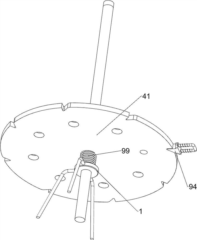
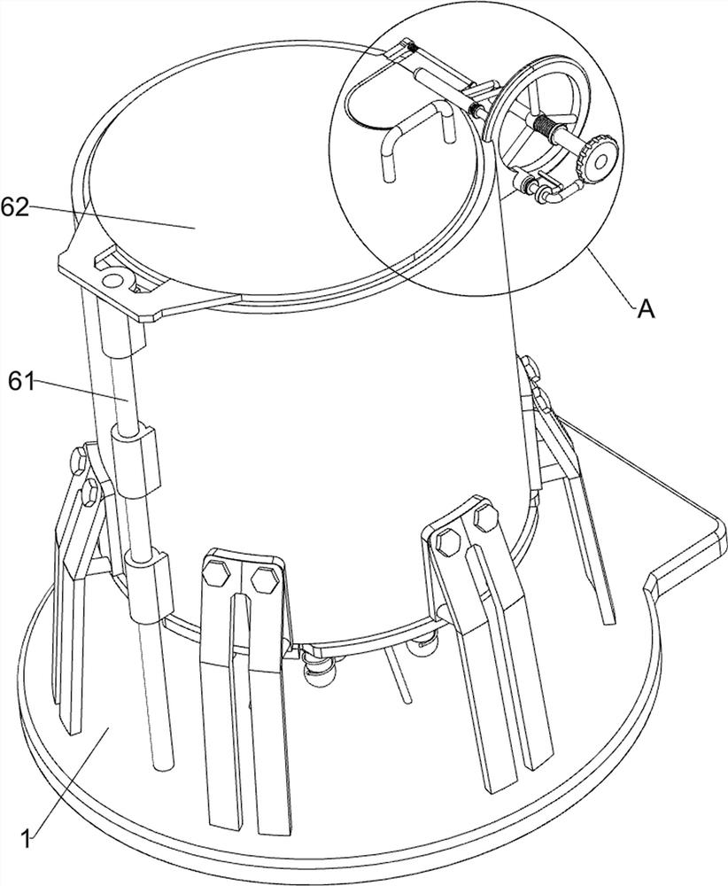
[0029] A closed gynecological vaginal expanding rod storage device, such as Figure 1 to Figure 5 As shown, it includes a base 1, a bracket 2, a cover cylinder 3, a shaft rod 4 and a first turntable 41. The top of the base 1 is connected with a plurality of brackets 2 evenly spaced along the circumferential direction, and a cover is connected between the plurality of brackets 2. The cylinder 3, the top of the base 1 is rotatably connected with a shaft 4, the lower part of the shaft 4 is connected with a first turntable 41, the first turntable 41 is located under the cover cylinder 3, and also includes a clamping component 5, a cover component 6, a support The retaining component 7 and the ejecting component 8 are provided with a clamping component 5 on the cover cylinder 3, a cover component 6 and an ejecting component 8 are provided on the base 1, and a supporting component is provided between the shaft 4 and the first turntable 41. Component 7.

[0030] The clamping assembl...

Embodiment 2

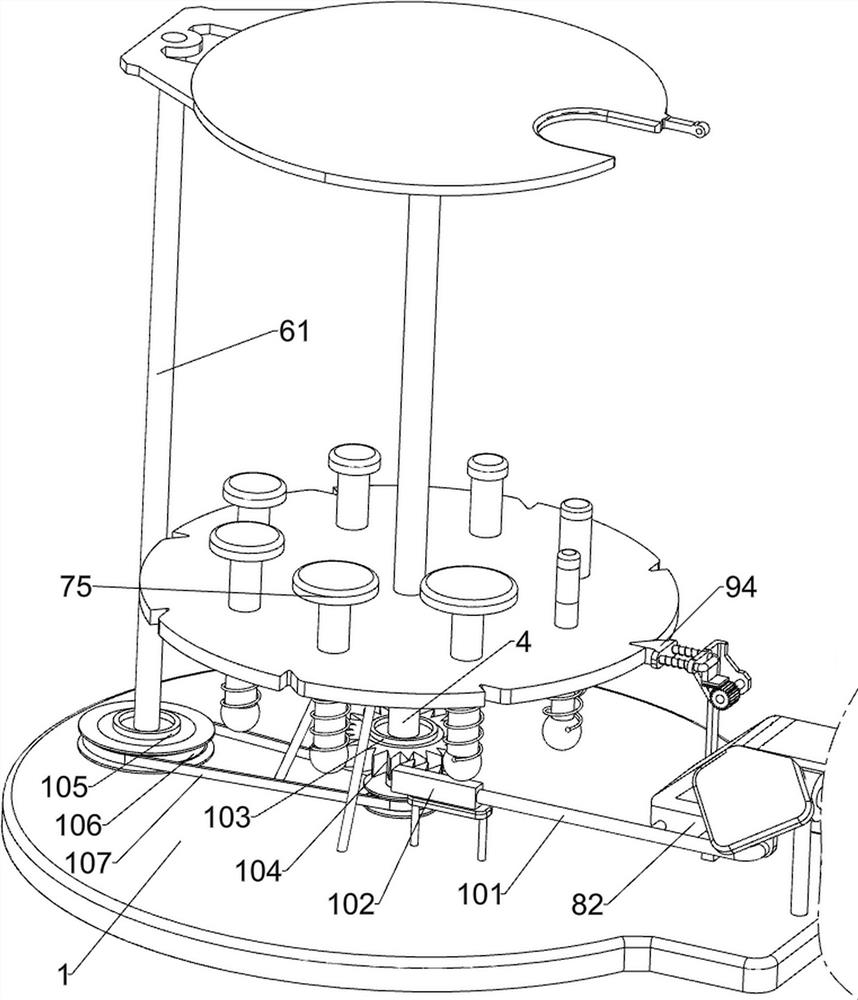
[0037] On the basis of Example 1, as Figure 5 As shown, it also includes a rotating assembly 10. The rotating assembly 10 includes a connecting rod 101, a straight rack 102, a first one-way clutch 103, a transmission gear 104, a second one-way clutch 105, a pulley 106 and a flat belt 107. The first A connecting rod 101 is connected to the wedge block 82, a straight rack 102 is connected to the connecting rod 101, a first one-way clutch 103 is connected to the lower part of the shaft rod 4, a transmission gear 104 is connected to the first one-way clutch 103, and the lower part of the rotating shaft 61 A second one-way clutch 105 is connected, and a pulley 106 is connected to the second one-way clutch 105 and the shaft 4. The pulley 106 on the second one-way clutch 105 is larger than the pulley 106 on the shaft 4. A flat belt 107 is wound therebetween.

[0038] When the first wedge block 82 moves to the right, the connecting rod 101 drives the straight rack 102 to move to the...

Embodiment 3

[0040] On the basis of Example 2, as Figure 4 and Image 6 As shown, it also includes a force accumulating assembly 9. The force accumulating assembly 9 includes a mounting frame 92, a sliding frame 93, a second wedge block 94, a compression spring 95, a transmission rack 96, a cylindrical gear 97, a drive rack 98 and a first Three torsion springs 99, the first turntable 41 is evenly spaced with eight card slots 91 in the circumferential direction, the top left side of the base 1 is connected with a mounting frame 92, the mounting frame 92 is slidably connected with a sliding frame 93, and the sliding frame 93 A second wedge-shaped block 94 is connected to the upper, and the second wedge-shaped block 94 is matched with the slot 91. A compression spring 95 is connected between the second wedge-shaped block 94 and the mounting frame 92, and a transmission rack 96 is connected to the second wedge-shaped block 94. The upper part of the mounting frame 92 is rotatably connected wi...


PUM


Abstract

The invention relates to a storage device, in particular to a closed gynecological vaginal dilating rod storage device. The technical problem to be solved by the present invention is how to design a closed gynecological vaginal dilating rod storage device that does not need to be fully opened for taking out. In order to solve the above technical problems, the present invention provides such a closed gynecological vaginal dilating rod storage device, which includes: a base, the top of which is connected with a plurality of brackets at uniform intervals along the circumferential direction; a cover tube, which is connected in multiple between the brackets; a shaft rod, which is rotatably connected to the top of the base, and a first turntable is connected to the lower part of the shaft rod; a clamping component, which is arranged on the cover cylinder; a cover component, which is arranged on the base. The invention stores the vaginal expanding rod through the cooperative operation of the clamping component, the covering component, the holding component and the ejecting component, so as to achieve the effect of storing the vaginal expanding rod.

Description

technical field [0001] The invention relates to a storage device, in particular to a closed gynecological vaginal dilating rod storage device. Background technique [0002] In the hospital, gynecology is a more important department. When examining patients, gynecology usually needs to use vaginal expansion rods to expand the vagina, so that doctors can better observe. The vaginal expansion rods need to be stored after use. [0003] After retrieval, the authorized patent publication number is CN211355917U, which discloses a classified storage box for vaginal dilating rods for gynecological surgery, including a base, a sleeve and a top cap, and the inner wall of one end of the sleeve is connected with the top cap through threads. , the inner wall of the other end of the sleeve is connected with the base through threads, the bottom surface of the inner wall of the base is fixedly connected with a rotating shaft, the outer surface of one end of the rotating shaft is movably conn...

Claims


Application Information

Patent Timeline
Patent Type & Authority Patents(China)
IPC IPC(8): A61B50/31A61B50/20F16F15/067
CPCA61B50/31A61B50/20F16F15/067A61B2050/0051A61B2050/0067A61B2050/3011
Inventor 刘红梅刘晓玲许旭柳素华
Owner QINGDAO WOMEN & CHILDREN HOSPITAL
Why Eureka
Try Eureka