
Pile driver for hook plate pile

A technology of pile driver and hook plate, which is applied to sheet pile walls, cleaning methods using tools, cleaning methods and appliances, etc., can solve the problems of reducing the working efficiency of pile drivers, cumbersomeness, and poor limit effect of hook sheet piles, etc., to achieve The effect of improving usability and work efficiency

Active Publication Date: 2022-02-11
无锡市聚英机械制造有限公司
View PDF4 Cites 0 Cited by
  • Summary
  • Abstract
  • Description
  • Claims
  • Application Information

AI Technical Summary

Problems solved by technology

[0004] The purpose of the present invention is to solve the problem in the prior art that the traditional pile driver has a poor position-limiting effect on the hook sheet pile, requiring the operator to hold the hook sheet pile to prevent it from swinging. This process is relatively cumbersome, and the operator is located The position of the hook sheet pile is fixed under the plate installation, which has great potential safety hazards and takes a long time, which reduces the working efficiency of the pile driver to a certain extent. A pile driver for hook sheet piles is proposed

Method used


Image

  • Pile driver for hook plate pile
  • Pile driver for hook plate pile
  • Pile driver for hook plate pile

Examples


Embodiment 1

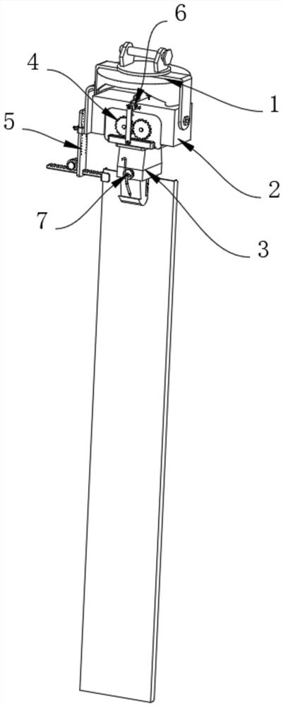
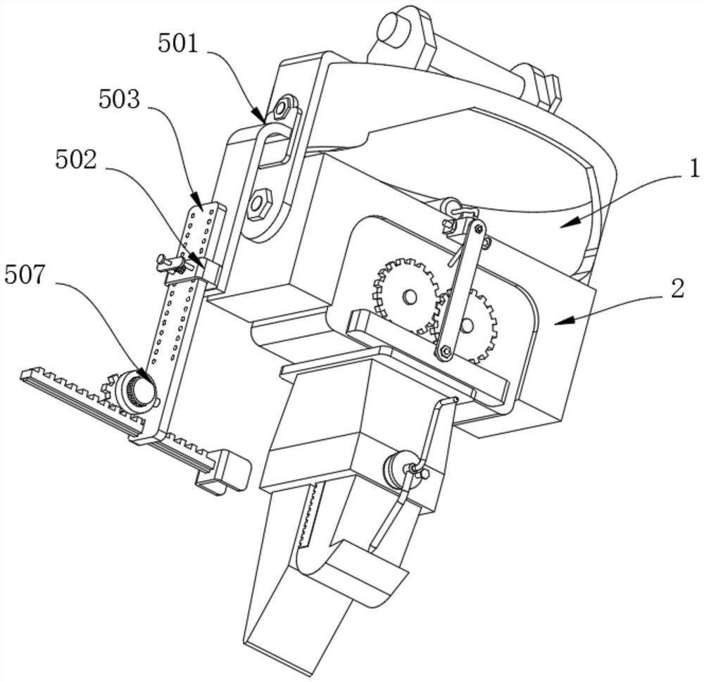
[0030] Example 1, such as Figure 1-8 As shown, the present invention provides a pile driver for a hook pile, including a hanger 1 and a limiting structure 5, and the lower end of the hanger 1 is rotated and mounted, and the lower end of the driver 2 is mounted with a holder 3, The surface of the driver 2 is mounted with two drive wheels 4, and the two drive wheels 4 mesh each other, the surface of the hanger 1 is provided with a limiting structure 5, and the surface of the driver 2 is provided with a lubricating structure 6, and the surface of the holder 3 is provided. Clean up structure 7.

[0031] The specific setting and action of its limit structure 5, the lubricating structure 6, and the cleaning structure 7 is specifically described below.

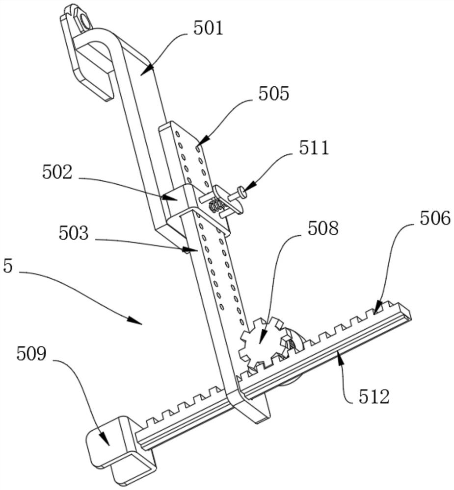
[0032] like image 3 andFigure 4 , The retaining structure 5 comprises a holder 501, the holder 501 is secured to the surface by means of a bolt of the hanger 1, the solid surface mount ring 502 with stop 501, the stop ring 502 is slidabl...

Embodiment 2

[0038] Example 2, on the basis of Example 1, the surface of the holder 3 is provided with cleaning structure 7, the structure 7 comprises a turntable 71 clean, turntable 71 is rotatably connected to the surface, the surface of the turntable 71 the holder 3 with solid scraping rods 72, 72 remote from the rod-end 71 of the turntable as a tip, the surface of the turntable 71 is inserted a threaded screw 73 is provided with the holder 3 corresponds to the position of the screw 73 with a solid rubber pad 74, may reach the clamper 3 claw stained with dirt simple cleaning effect, and does not require clean-up may be temporary housing fixed scraping effect on the lever 72, the side away from the drive wheel 71 fixedly arranged on the handle 2 of 75, 75 of the handle cross-section as a "Z" shape, that can be reached rapidly rotating disk 71, rotating disk 71 driven by the rod-effect of the mobile 72, and after a long time use of the holder 3, the holder 3 due to the hook clamp stop hook sh...


PUM


Abstract

The invention provides a pile driver for a hook plate pile, and relates to the technical field of pile drivers, the pile driver comprises a hanging bracket and a limiting structure, the lower end of the hanging bracket is rotatably provided with a driver, the lower end of the driver is provided with a clamping device, the surface of the driver is provided with two driving wheels, and the two driving wheels are engaged with each other; a limiting structure is arranged on the surface of the hanging bracket and comprises a fixing frame, the fixing frame is fixedly installed on the surface of the hanging bracket through bolts, a limiting ring is fixedly installed on the surface of the fixing frame, and a sliding plate is slidably connected to the inner wall of the limiting ring. The device solves the problems that the limiting effect of a traditional pile driver on a hook plate pile is poor, an operator needs to hold the hook plate pile to prevent the hook plate pile from swinging, the process is tedious, the operator is located below a scraper to fix the position of the hook plate pile, potential safety hazards are large, consumed time is long, and the working efficiency of the pile driver is reduced to a certain extent.

Description

Technical field [0001] The present invention relates to the field of pile driver, and more particularly to a pile driver for a hook pile. Background technique [0002] The pile driver is a heavy machine, and the pile hammer is attached between the two parallel vertical guide rods in front of the pile frame, hoisting with lift hooks, and the pile driver can also lift the hook pile to insert the foundation pit inserted into the ground. Among the common large construction machinery. [0003] When using the pile driver to hang the hook pile, the hook pile is susceptible to the inertia, and the traditional pile driver is poor to the hook pile, and the operator needs to hold the crochement. The pile hinders its swing, and then assist the pile driver to insert the pile of the foundation pit of the ground. This process is more cumbersome, and the operator is located in the scraper to fix the hook pile position, the safety hazard is large, costly Time is longer, and the work efficiency of...

Claims


Application Information

Patent Timeline
Patent Type & Authority Applications(China)
IPC IPC(8): E02D7/06E02D7/14E02D13/00E02D13/04B08B1/00B08B1/04
CPCE02D7/06E02D7/14E02D13/00E02D13/04B08B1/165B08B1/32
Inventor 莫少华
Owner 无锡市聚英机械制造有限公司
Learn More