Arrangement, method and computer program product for limiting circulating currents

a technology of circulating current and computer program, which is applied in the field of voltage source converters, can solve the problems of high power level, flow of circulating current in the converter, and semiconductor devices used in the converters being operated at their maximum voltage and current limits, etc., and achieves the effects of reducing computational burden, increasing the power rating of the first converter, and reducing losses in the dc transmission system

Active Publication Date: 2018-08-14
HITACHI ENERGY LTD
View PDF15 Cites 2 Cited by
  • Summary
  • Abstract
  • Description
  • Claims
  • Application Information

AI Technical Summary

Benefits of technology

[0015]The present invention has a number of advantages. Through the control a fast limitation of the circulating current is achieved. This reduces losses in and increases the stability of the DC transmission system. Thereby also the power rating of the first converter may be increased. The use of the average of the two arm currents in the control does for instance force the two arm current to be equal. The control has a number of additional advantages. It may be implemented with only a few additional components or a few additional computer instructions. Thereby the computational burden is low. The control is also based on directly measured currents without any estimations.

Problems solved by technology

Furthermore, in these systems the power levels keep getting higher.
However, semiconductor devices used in the converter are often being operated at their maximum voltage and current limits.
However, even a small mismatch between the parameters of both the arms leads to a flow of circulating current in the converter.
This causes an imbalance in the distribution of load current between different phases leading to additional losses or instability in the system.
This is one of the important issues in paralleling of converter arms.

Method used


Image

  • Arrangement, method and computer program product for limiting circulating currents
  • Arrangement, method and computer program product for limiting circulating currents
  • Arrangement, method and computer program product for limiting circulating currents

Examples


Embodiment Construction

[0022]In the following, a detailed description of preferred embodiments of the invention will be given.

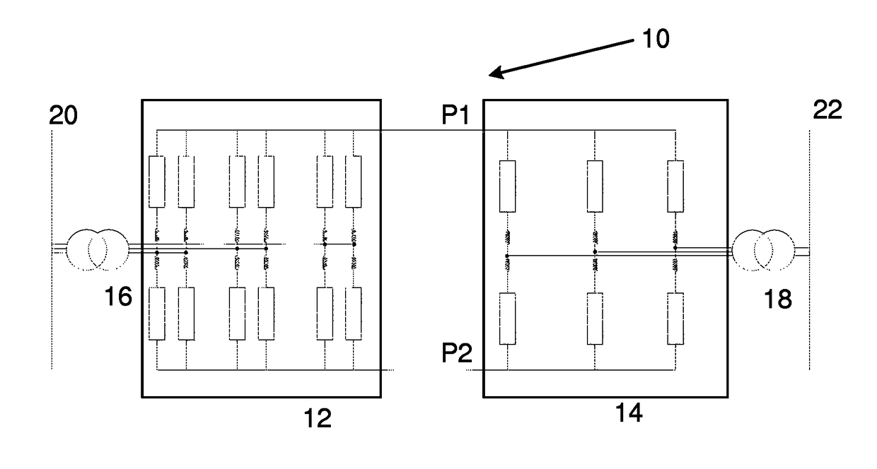
[0023]FIG. 1 shows a simplified Direct Current (DC) power transmission system 10 comprising a first converter 12 and a second converter 14, where the two converters 12 and 14 are interconnected by two DC pole lines P1 and P2. The first converter 12 is here be connected to a first alternating Current (AC) power transmission system 20 via a first transformer 16, and the second converter 14 may be connected to a second AC power transmission system 22 via a second transformer 18.

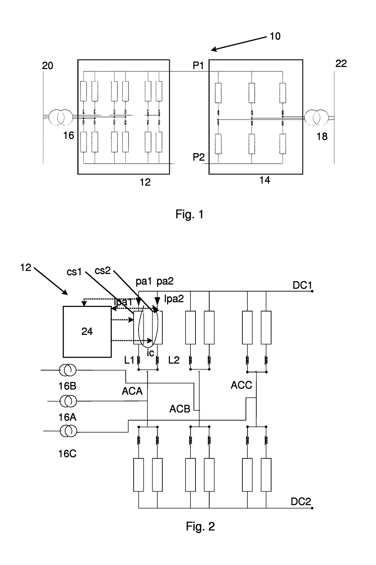
[0024]The converters 12 and 14 are both voltage source converter and more particularly multilevel converters comprising cells, i.e. voltage source converters employing cells for forming multiple voltage levels. The conversion is in this example furthermore made between DC and three-phase AC. Therefore, both converters have three phase legs, one for each phase.

[0025]In the second converter 14 each phase leg is d...


PUM


Abstract

An arrangement, method and computer program product are provided for limiting circulating currents in a converter converting between AC and DC. The converter has a number of AC and DC terminals and includes a number of converter arms, where a first and a second converter arm are connected in parallel between a first DC terminal and a first AC terminal. Each converter arm includes a string of series-connected converter cells. The arrangement includes a control unit that obtains a current of the first converter arm and a current of the second converter arm, forms an average of the two converter arm currents, forms a first and a second voltage control signal based on the average and uses the first and second voltage control signal in the control of the voltage provided by the first and second converter arm.

Description

FIELD OF INVENTION[0001]The present invention generally relates to voltage source converters. More particularly the present invention relates to an arrangement, method and computer program product for limiting circulating currents of converters.BACKGROUND[0002]Direct Current (DC) power transmission systems are of interest to use in various situations, for instance when transferring electrical power over long distances.[0003]High Voltage Direct Current (HVDC) transmission of power has proved to be an efficient alternative to Alternating Current (AC) transmission in many power transmission situations. Several HVDC transmission lines may furthermore be interconnected to form an HVDC transmission network.[0004]These power systems are typically equipped with converters for converting between AC and DC. Furthermore, in these systems the power levels keep getting higher.[0005]With the increase in the power levels being transmitted over HVDC systems, a need to enhance the power rating of th...

Claims


Application Information

Patent Timeline
Patent Type & Authority Patents(United States)
IPC IPC(8): H02M7/04H02M7/12H02J3/36
CPCH02M7/12H02J2003/365H02J3/36H02M7/483H02M7/493H02M7/4835
Inventor KALLURI, SRI RAMYAKASAL, GAURAV-KUMARJIANG-HAFNER, YINGHAFNER, JURGEN
Owner HITACHI ENERGY LTD
Why Eureka
Try Eureka