Automatic conveying device

A technology of automatic conveying device and electric telescopic rod, which is applied in the direction of supply configuration, combustion method, block/powder supply/distribution, etc., can solve problems such as inconvenient use, and achieve the effect of avoiding fuel shortage

Inactive Publication Date: 2019-08-16
江苏久协仪器科技有限公司
View PDF7 Cites 0 Cited by
  • Summary
  • Abstract
  • Description
  • Claims
  • Application Information

AI Technical Summary

Problems solved by technology

[0003] The purpose of the present invention is to provide an automatic conveying device, which has the advantage of automatically filling fuel into the boiler, and solves the problem that it is inconvenient for people to use it because it needs to manually fill the boiler all the time.

Method used


Image

  • Automatic conveying device
  • Automatic conveying device
  • Automatic conveying device

Examples


Embodiment Construction

[0017] The following will clearly and completely describe the technical solutions in the embodiments of the present invention with reference to the accompanying drawings in the embodiments of the present invention. Obviously, the described embodiments are only some, not all, embodiments of the present invention. Based on the embodiments of the present invention, all other embodiments obtained by persons of ordinary skill in the art without making creative efforts belong to the protection scope of the present invention.

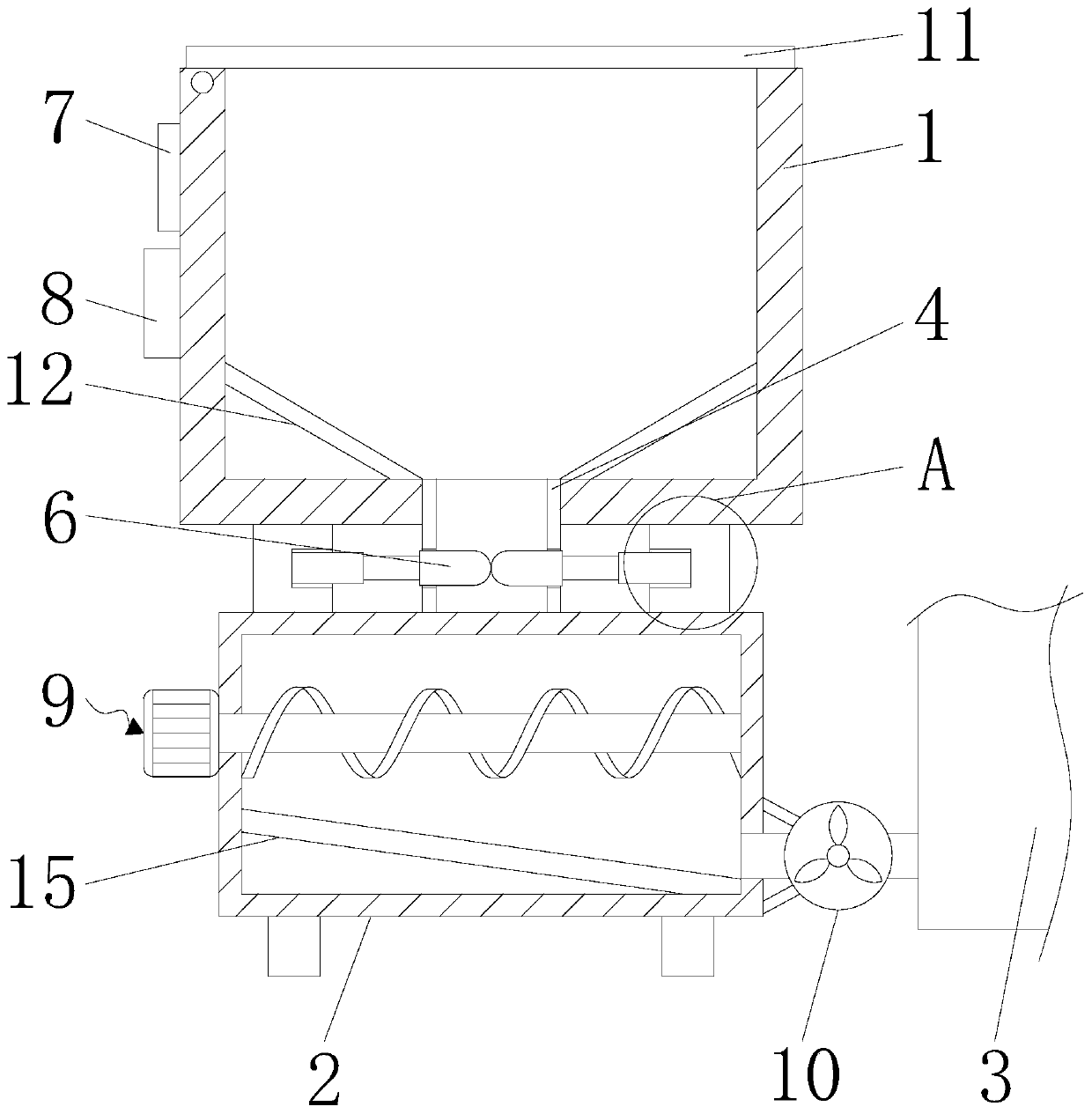
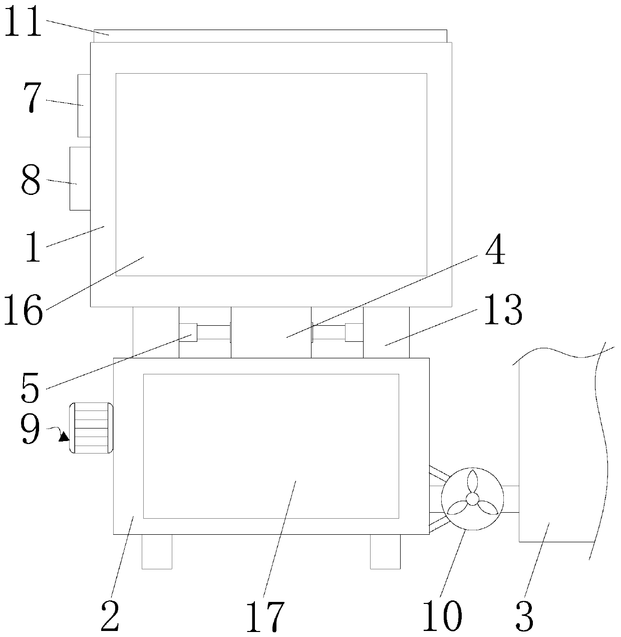
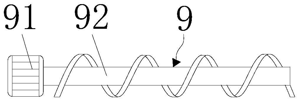
[0018] see Figure 1-4 , an automatic conveying device, including a box body 1, a crushing box 2 and a combustion chamber 3, the top of the box body 1 is movably connected with a cover plate 11 through a rotating shaft, through the cover plate 11, the effect of sealing the box body 1 is achieved to avoid impurities Falling into the box body 1 will affect the combustion effect, and both sides of the bottom of the inner cavity of the box body 1 are fixedly conne...


PUM


Abstract

The invention discloses an automatic conveying device. The automatic conveying device comprises a box body, a crushing box and a combustion chamber; the bottom of the box body communicates with a connecting pipe; the bottom of the connecting pipe communicates with the crushing box; electric extension rods are arranged on two sides of the bottom of the box body; one ends of the electric extension rods are fixedly connected with baffle plates; and the ends, far from the electric extension rods, of the baffle plates extend into the connecting pipe. The box body is provided to achieve a fuel storage effect; through the connecting pipe, an effect of connecting the box body with the crushing box is achieved; through the electric extension rods, an effect of driving the baffle plates to move is achieved; through the baffle plates, an effect of sealing the connecting pipe is achieved; through a crushing mechanism, an effect of crushing fuels is achieved; through a fan, an effect of conveying the fuels into the combustion chamber is achieved; through a timer, an effect of starting or stopping the electric extension rods and the fan at regular time is achieved; and the conveying device can automatically inject the fuels in a boiler, so that the use is convenient by people.

Description

technical field [0001] The invention relates to the technical field of hot water boiler feeding, in particular to an automatic conveying device. Background technique [0002] Hot water boilers can be divided into electric hot water boilers, oil-fired hot water boilers, gas-fired hot water boilers, coal-fired hot water boilers, etc. according to different fuels. Boilers need to use fuel when they are in use. The fuel is usually straw, straw, etc., but the existing The fuel cannot be sufficiently crushed, and it is prone to insufficient combustion, and the fuel cannot be delivered. For example, a Chinese patent discloses a hot water boiler fuel delivery device (patent number: 201810166449.3). The setting can filter the pulverized fuel to ensure the utilization of resources. The spacer is set with rubber material, which provides fuel buffer and effectively protects the delivery box. The setting of universal wheels makes the device move more conveniently. The observation port c...

Claims


Application Information

Patent Timeline
Patent Type & Authority Applications(China)
IPC IPC(8): F23K3/02F23N1/00B02C19/22
CPCB02C19/22F23K3/02F23K2203/201F23N1/005
Inventor 邱爱兵王春
Owner 江苏久协仪器科技有限公司
Why Eureka
Try Eureka