A blade-type fast mechanical-optic switch based on piezoelectric actuation

A piezoelectric drive, blade technology, applied in optics, optical components, instruments, etc., can solve the problems of slow response, small clear aperture, slow switching speed, etc., to save manpower and material costs, reduce displacement stroke requirements , the effect of improving the efficiency of use

Active Publication Date: 2022-04-22
SHANDONG UNIV
View PDF21 Cites 0 Cited by
  • Summary
  • Abstract
  • Description
  • Claims
  • Application Information

AI Technical Summary

Problems solved by technology

At present, the mainstream mechanical optical switches have some shortcomings of their own. The more prominent problem is that the switching speed is relatively slow, usually above 10 milliseconds. This is mainly because most mechanical optical switches are driven by electric motors, resulting in slow response.
In order to achieve fast switching of the beam, some mechanical optical switches use thin metal sheets as action shutters. Because the thin metal sheets are light in weight, this helps to improve the response speed, but the metal sheets cannot withstand high-power lasers, and the light hole is small. In addition, because the traditional motor drive method is still used, there is also obvious vibration and noise when performing switching actions, which limits its use in places that require low noise and high power work. In addition, the response speed of this type of switch is also very high. Limited, the best can only reach about ten milliseconds
There are also mechanical optical switches that use one or more rotating motors for switching operations. The switching speed can reach the microsecond level, but certain vibrations are generated when the on / off operation is performed, and the light aperture is small, so the beam needs to be focused before use. , which requires more lenses and extremely careful calibration. In addition, this kind of switch is too bulky to be suitable for miniaturized optical paths.

Method used


Image

  • A blade-type fast mechanical-optic switch based on piezoelectric actuation
  • A blade-type fast mechanical-optic switch based on piezoelectric actuation

Examples


Embodiment Construction

[0020] The present invention will be described in detail below in conjunction with the accompanying drawings and embodiments.

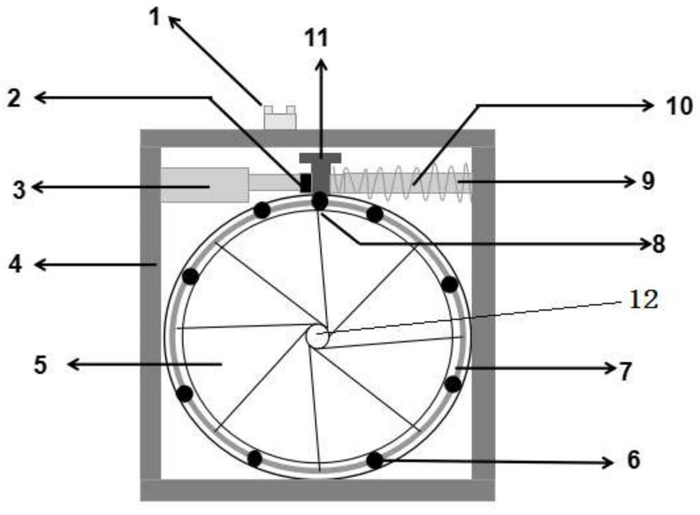
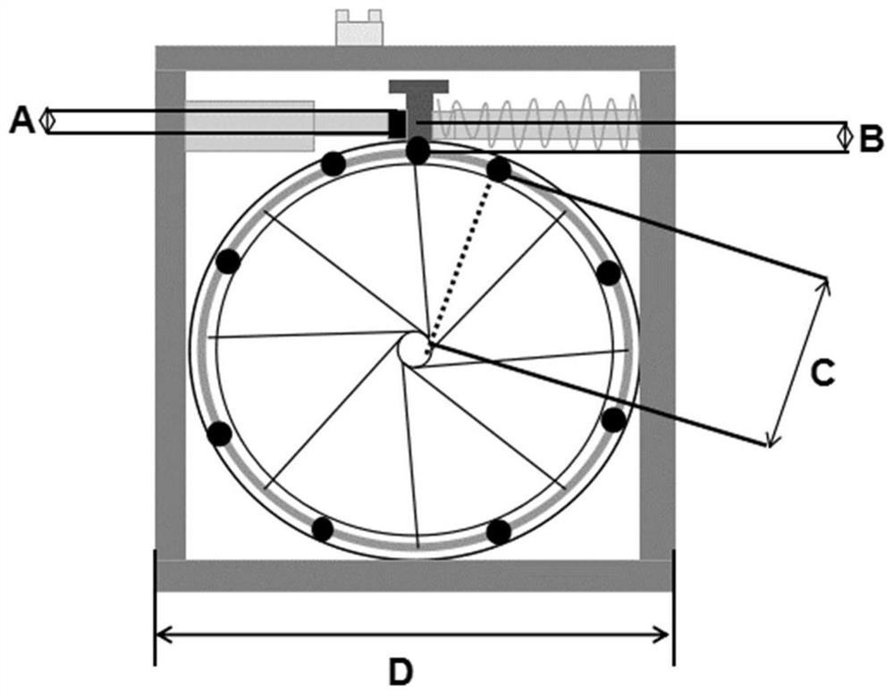
[0021] A blade-type fast mechanical optical switch based on piezoelectric drive, including an aperture diaphragm and a piezoelectric ceramic stack 2, the aperture diaphragm includes eight metal blades 5, and the metal blades 5 are fixed in a fixed snap ring 7, both Fixed by the fixing screw 6 , one end of the blade control rod 11 is fixed on the fixing snap ring 7 by the main fixing screw 8 , and the other end is in contact with the piezoelectric ceramic stack 2 . When the aperture diaphragm is opened, all the metal blades 5 can spread out around the light hole and around the fixed snap ring 7 . The aperture diaphragm is installed inside the metal housing 4, and the two sides of the blade control rod 11 of the aperture diaphragm are respectively provided with a piezoelectric ceramic stack 2 and a return spring 10, and the piezoelectric ceramic stack 2...


PUM


Abstract

The invention relates to a blade-type fast mechanical optical switch driven by piezoelectricity, which mainly includes an aperture diaphragm and a stack of piezoelectric ceramics, the aperture diaphragm is installed inside a metal casing, and the blade control rod of the aperture diaphragm There are piezoelectric ceramic stacks and return springs on both sides, the distance from the aperture of the aperture diaphragm to its fixing screw is greater than the distance between the piezoelectric ceramic stack and the main fixing screws of the aperture diaphragm, and the pressure The electroceramic stack is connected to an external power source. Its advantage is that it overcomes the problem of slow response speed of mechanical optical switches in the past, and there is no loss of transmitted light optical power, and the optical path does not change, which greatly simplifies the optical path, saves manpower and material costs, and improves the use efficiency of the laser. , so that it can meet the current application requirements in fields such as precision measurement physics and quantum optics experiments that have extremely high requirements for the response speed of mechanical switches.

Description

technical field [0001] The present application relates to the field of optical switches, in particular to a blade-type fast mechanical optical switch driven by piezoelectricity. Background technique [0002] Commonly used mechanical optical switches mainly rely on thermal, electric, magnetic and other driving methods to use the mechanical movement of objects to let go or block light, so as to realize the on / off operation of light. At present, the mainstream mechanical optical switches have some shortcomings of their own. The more prominent problem is that the switching speed is relatively slow, usually above 10 milliseconds. This is mainly because most mechanical optical switches are driven by electric motors, resulting in slow response. In order to achieve fast switching of the beam, some mechanical optical switches use thin metal sheets as action shutters. Because the thin metal sheets are light in weight, this helps to improve the response speed, but the metal sheets cann...

Claims


Application Information

Patent Timeline
Patent Type & Authority Patents(China)
IPC IPC(8): G02B26/02
Inventor 王立勇赵显李志强
Owner SHANDONG UNIV
Why Eureka
Try Eureka