Vehicle lane changing method and related equipment

A vehicle and lane technology, applied in the field of automatic driving, can solve the problems of large calibration processing work, many calibration parameters, and inability to better meet safety requirements, so as to reduce the driving parameters of the calibrated vehicle, improve comfort and stability, The effect of enhancing the ride experience

Active Publication Date: 2021-04-16
HUAWEI TECH CO LTD
View PDF6 Cites 4 Cited by
  • Summary
  • Abstract
  • Description
  • Claims
  • Application Information

AI Technical Summary

Problems solved by technology

[0003] However, this function still requires the driver to concentrate on initially selecting the lane-changing gap (lane-changing Gap) for lane-changing and inserting vehicles, and then perform lane-changing and inserting on the selected lane-changing Gap according to road conditions. Generally, the default is The nearest lane-changing Gap on the adjacent lane of the self-vehicle is used for lane-changing and interpolation
Therefore, the following problems still exist in the selection of the vehicle’s active lane change Gap: the driver still needs to choose the lane change Gap independently. need
Especially when the vehicle on the side lane is parallel to the own vehicle, and the vehicle condition is complicated, the default is the nearest lane-changing Gap on the adjacent lane of the own vehicle, which is used to change lanes and insert vehicles, which can easily lead to traffic safety accidents
However, in the prior art, when it is necessary to select the lane-changing gap according to the road conditions for lane-changing and inserting vehicles, many calibration parameters are required, and the post-calibration processing work is large, and it is easy to miss the best lane-changing opportunity; moreover, this method requires high traffic flow stability. , the vehicles in the target lane need to be in a stable state for a long time to prevent safety accidents

Method used


Image

  • Vehicle lane changing method and related equipment
  • Vehicle lane changing method and related equipment
  • Vehicle lane changing method and related equipment

Examples


Embodiment Construction

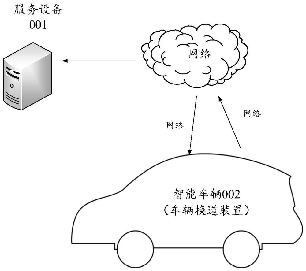
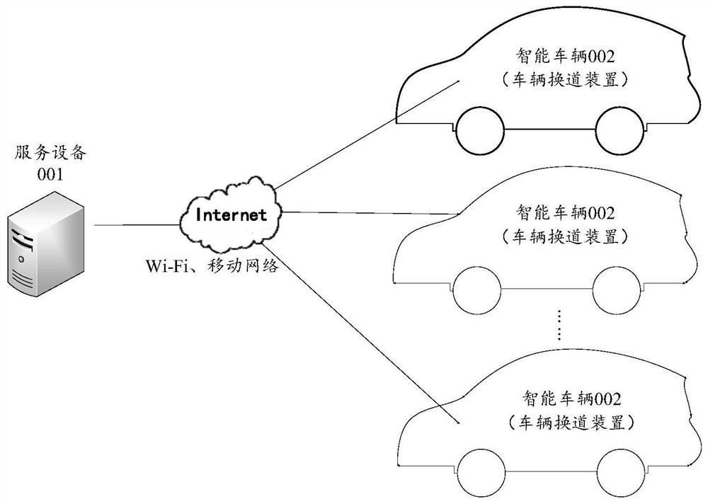
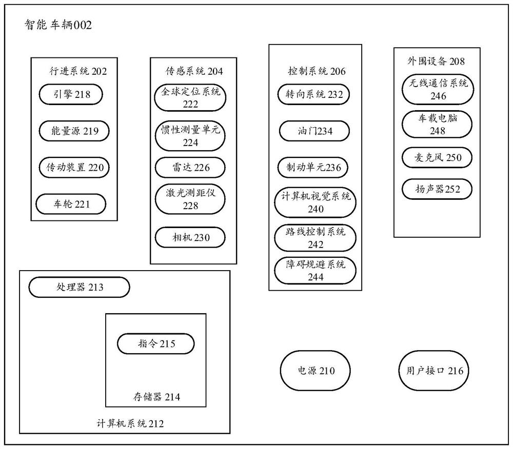
[0061] The embodiments of the present application will be described below with reference to the drawings in the embodiments of the present application.

[0062] The terms "first" and "second" in the description and claims of the present application and the drawings are used to distinguish different objects, rather than to describe a specific order. Furthermore, the terms "include" and "have", as well as any variations thereof, are intended to cover a non-exclusive inclusion. For example, a process, method, system, product or device comprising a series of steps or units is not limited to the listed steps or units, but optionally also includes unlisted steps or units, or optionally further includes For other steps or units inherent in these processes, methods, products or apparatuses.

[0063] Reference herein to an "embodiment" means that a particular feature, structure, or characteristic described in connection with the embodiment can be included in at least one embodiment of...


PUM


Abstract

The invention discloses a vehicle lane changing method and device, and the method comprises the following steps: obtaining the current speed of a target vehicle, N lane changing Gaps on a target lane, and the Gap attribute corresponding to each lane changing Gap; according to the mapping relation between each lane changing Gap template in the Gap template set and the vehicle speed, obtaining M lane changing Gap templates matched with the current speed from the Gap template set; obtaining a target lane changing Gap and a target lane changing Gap template from the N lane changing Gap templates and the M lane changing Gap templates, wherein the similarity between the Gap attribute corresponding to the target lane changing Gap and the preset Gap attribute corresponding to the target lane changing Gap template is the highest; and controlling the target vehicle to change the lane to the target lane change Gap through the target lane change Gap template. When the vehicle is driven, the lane changing section can be accurately and efficiently selected for driving.

Description

technical field [0001] The present application relates to the technical field of automatic driving, in particular to a vehicle lane changing method and related equipment. Background technique [0002] Changing lanes at high speeds is a high-risk driving behavior, which will extremely test the driver's attention and control, and a little inattentiveness may lead to tragedy. In order to improve the safety of high-speed lane changes, most of the existing models are equipped with auxiliary devices such as Driver Assistance Systems (ADAS), which can be triggered by the turn signal lever to actively change lanes. [0003] However, this function still requires the driver to concentrate on initially selecting the lane-changing gap (lane-changing Gap) for lane-changing and inserting vehicles, and then perform lane-changing and inserting on the selected lane-changing Gap according to road conditions. Generally, the default is The nearest lane-changing Gap on the adjacent lane of the ...

Claims


Application Information

Patent Timeline
IPC IPC(8): B60W30/18B60W40/02B60W40/105
CPCB60W30/18B60W40/105B60W40/02
Inventor 曾侠杜明博
Owner HUAWEI TECH CO LTD
Why Eureka
Try Eureka