Continuous stamping method without landing edge

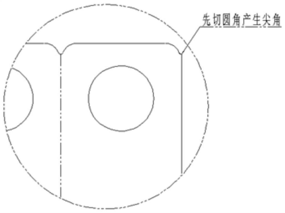
A technology without lapping and punching, which is applied in the field of stamping and can solve the problems of low material utilization rate and sharp corners of cutting fillets

Pending Publication Date: 2021-04-20
东风汽车零部件集团有限公司通用铸锻分公司
View PDF7 Cites 0 Cited by
  • Summary
  • Abstract
  • Description
  • Claims
  • Application Information

AI Technical Summary

Problems solved by technology

[0006] In view of the problems existing in the background technology, the purpose of the present invention is to solve the problem of low utilization rate of materials, and can well solve the problem of sharp corners produced by rounded corners

Method used


Image

  • Continuous stamping method without landing edge
  • Continuous stamping method without landing edge
  • Continuous stamping method without landing edge

Examples


Embodiment Construction

[0053] pass below Figure 6 ~ Figure 15 As well as listing some optional embodiments of the present invention, the technical solutions (including preferred technical solutions) of the present invention are further described in detail. Apparently, the described embodiments are only some of the embodiments of the present invention, not all of them. Based on the embodiments of the present invention, all other embodiments obtained by persons of ordinary skill in the art without creative efforts fall within the protection scope of the present invention.

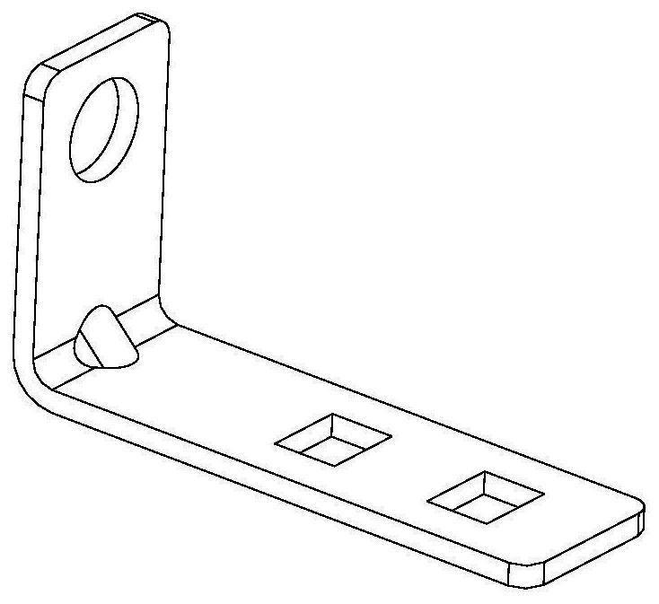
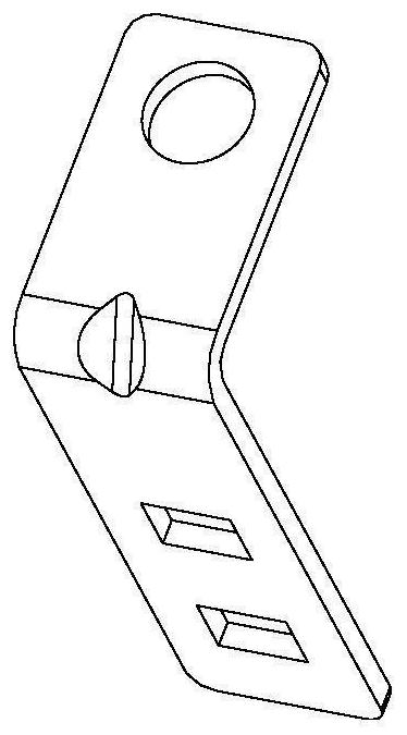
[0054] Such as Figure 6 to Figure 15 As shown, the non-overlapping continuous die is used for punching and forming an L-shaped bracket with rounded corners, including a punching die 1, a cutting die 2, a filleting die 3 and a bending die 4 arranged in sequence along the feeding direction.

[0055] Preferably, the punching die 1 punches one circular hole and two square holes on the blank 5, and all the punched circular holes are...


PUM


Abstract

The invention discloses a continuous stamping method without a landing edge. The continuous stamping method includes the following steps of: S1, completing punching required by a part on a blank according to design requirements of the part; S2, cutting off the blank according to a designed width; S3, cutting a round corner on the blank according to the design requirements of the part; S4, bending and ribbing the blank according to design requirements of the part; and S5, conducting discharging. According to the continuous stamping method disclosed by the invention, stock layout and components of a mold are optimized, and the key point is how to well feed materials under the condition of being separated from a carrier, how to cut fillets at the two ends after separation and how to feed materials in place.

Description

technical field [0001] The invention relates to the technical field of stamping, in particular to a continuous stamping method without overlapping. Background technique [0002] Such as figure 1 and figure 2 As shown, the L-shaped bracket product is a commonly used product with a wide range of applications, especially in the automotive industry. Generally, the precision grade of L-shaped bracket products is at T12 level, which belongs to parts with low precision requirements, and its size technical requirements are not high. The product has to be plasticized and painted. [0003] Such as image 3 As shown, at the same time, in the prior art, after the rounded corners of the product are cut, because the rounded corners are small, there will be sharp corners near the cut, which poses a safety hazard. [0004] Such as Figure 4 and Figure 5 As shown, the existing layout is to stagger the square holes and round holes of adjacent parts, and the arrangement distance betwe...

Claims


Application Information

Patent Timeline
IPC IPC(8): B21D35/00B21D37/08B21D45/02
Inventor 袁石华何柏林王学成杨立军沈有仓
Owner 东风汽车零部件集团有限公司通用铸锻分公司
Why Eureka
Try Eureka