
A step-bending lamination device for ship outfitting parts

An outfitting and lamination technology is applied in the field of step bending lamination devices for ship outfitting parts, which can solve the problems of shortening equipment life, easy damage of lamination shafts, and high maintenance costs of lamination shafts.

Active Publication Date: 2022-08-09
湖北江润造船有限公司
View PDF0 Cites 0 Cited by
  • Summary
  • Abstract
  • Description
  • Claims
  • Application Information

AI Technical Summary

Problems solved by technology

[0002] Laminating machine is a machine used to press and apply film on the surface of materials such as boards. When a general laminating machine is in use, after the film is finished, the workpiece such as the board to be laminated is separated from the two laminating shafts. The laminating shafts will move closer to each other under the action of the air pump, and they will fit together tightly under the action of pressure, which will cause damage to the laminating shafts under continuous pressure, reducing the life of the equipment, and the maintenance of the laminating shafts Higher cost, more costly
[0003] Aiming at the deficiencies of the prior art, the present invention provides a step bending lamination device for ship outfitting, which has the advantage of preventing the lamination shaft from being bonded and crushed, and solves the problem that the lamination shaft is easily damaged

Method used


Image

  • A step-bending lamination device for ship outfitting parts
  • A step-bending lamination device for ship outfitting parts
  • A step-bending lamination device for ship outfitting parts

Examples


Embodiment Construction

[0020] The technical solutions in the embodiments of the present invention will be clearly and completely described below with reference to the accompanying drawings in the embodiments of the present invention. Obviously, the described embodiments are only a part of the embodiments of the present invention, but not all of the embodiments. Based on the embodiments of the present invention, all other embodiments obtained by those of ordinary skill in the art without creative efforts shall fall within the protection scope of the present invention.

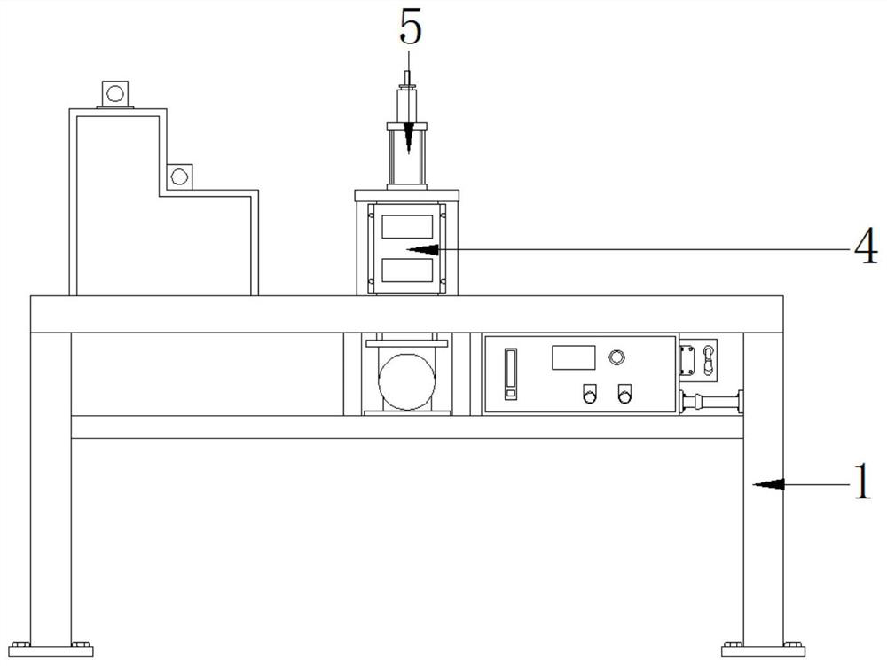
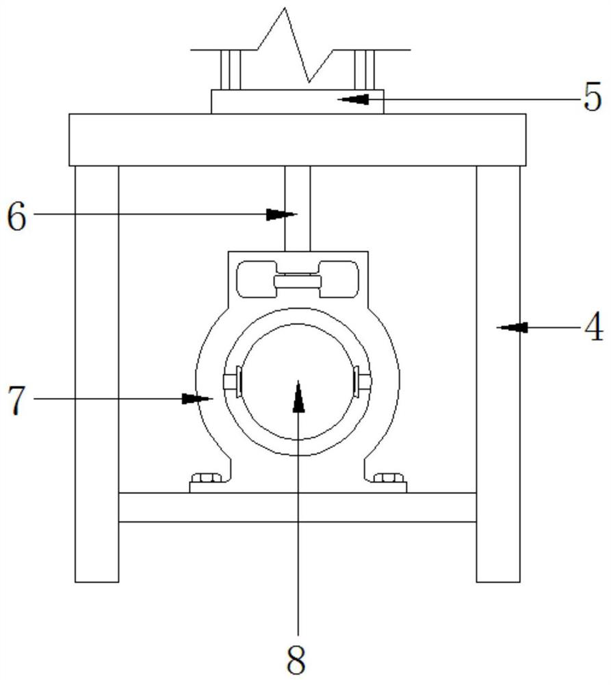
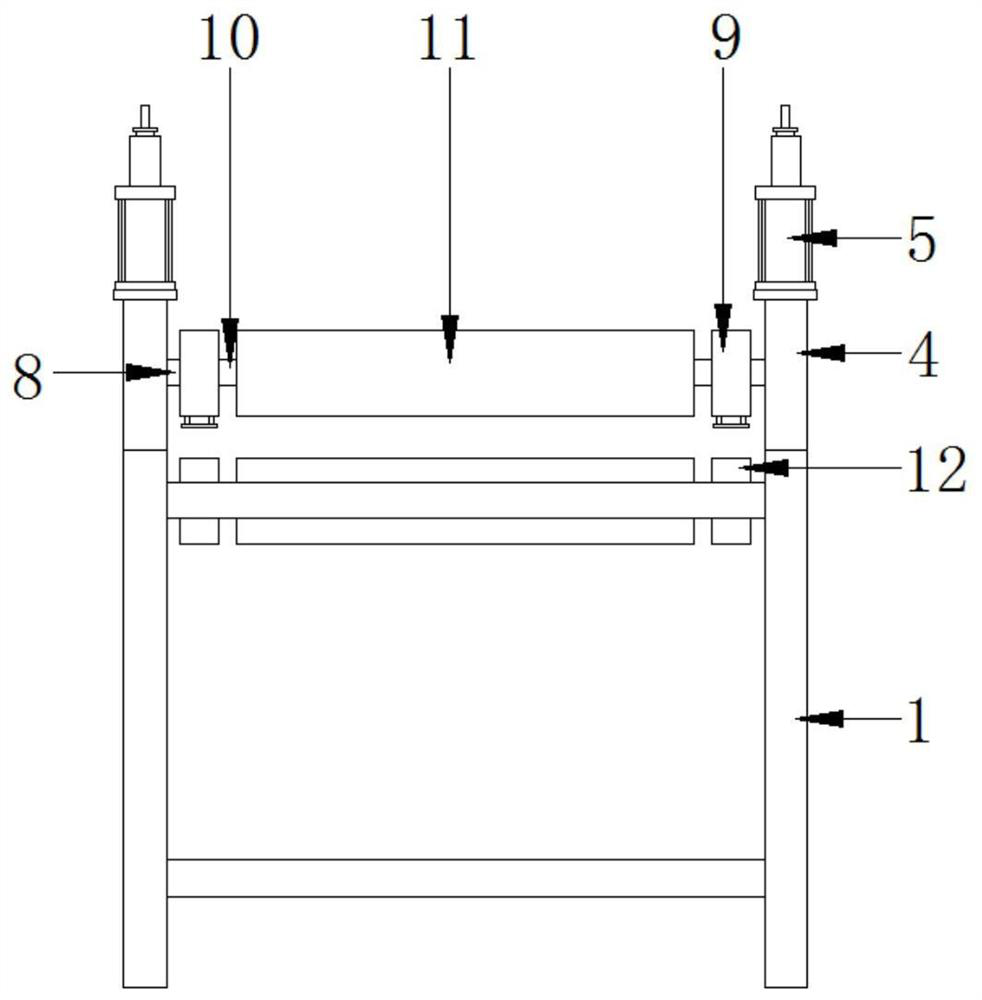
[0021] see Figure 1-3 , a step bending lamination device for ship outfitting parts, comprising a support frame 1, a control device 2 and a moving device 3, a side plate 4 is fixedly installed at the top of the support frame 1, an air pump 5 is fixedly installed at the top of the side plate 4, and the bottom of the air pump 5 is fixed An air pressure rod 6 is movably installed at the end, a sliding seat 7 is fixedly installed at the b...


PUM


Abstract

The invention relates to the technical field of laminating machines, and discloses a step-bending laminating device for ship outfitting parts, which includes a support frame, a control device and a moving device. An air pump is fixedly installed, an air pressure rod is movably installed at the bottom end of the air pump, a sliding seat is fixedly installed at the bottom end of the air pressure rod, a fixed shaft is fixedly installed inside the sliding seat, and a movable shaft is fixedly installed on the left side of the fixed shaft The left side of the movable seat is movably installed with a movable shaft, the left side of the movable shaft is fixedly installed with a lamination shaft, the top of the support frame is fixedly installed with a fixed seat, and the control device is movably installed inside the movable seat, The moving device is movably installed inside the moving seat, and the device can separate the two laminating shafts that are close to each other after the lamination is completed, so as to prevent the laminating shafts from sticking together under the action of pressure and avoiding being squeezed by pressure. , effectively protect the lamination shaft.

Description

technical field [0001] The invention relates to the technical field of laminating machines, in particular to a stepping bending laminating device for ship outfitting parts. Background technique [0002] The laminating machine is a machine used for pressing and laminating the surface of materials such as plates. When a general laminating machine is in use, after the lamination is completed, the workpieces such as the laminated plate are separated from the two lamination shafts. Under the action of the air pump, the lamination shafts will move closer to each other, and they will stick together tightly under the action of pressure. Under the continuous pressure, the lamination shaft will be damaged, which will reduce the life of the equipment and the maintenance of the lamination shaft. The higher the cost, the greater the cost. [0003] Aiming at the deficiencies of the prior art, the present invention provides a step-bending lamination device for ship outfitting parts, which...

Claims


Application Information

Patent Timeline
Patent Type & Authority Patents(China)
IPC IPC(8): B29C63/02B29C63/00
Inventor 高卓东
Owner 湖北江润造船有限公司
Learn More