A pressure-holding device and a key-press pressure-holding method

A device and key technology, applied in the fields of medical science, cleaning teeth, electrical components, etc., can solve the problem of detachment from the brush handle, etc., and achieve the effect of improving the efficiency of maintaining pressure, improving the detachment of the brush handle, and the uniformity of maintaining pressure.

Active Publication Date: 2022-06-28
SHENZHEN BAOLIJIE TECH CO LTD
View PDF5 Cites 0 Cited by
  • Summary
  • Abstract
  • Description
  • Claims
  • Application Information

AI Technical Summary

Problems solved by technology

[0005] In order to improve the even force of the button and install it on the brush handle, and improve the problem that the button is lifted and detached from the brush handle during use, the application provides a pressure maintaining device and a method for maintaining pressure on the button

Method used


Image

  • A pressure-holding device and a key-press pressure-holding method
  • A pressure-holding device and a key-press pressure-holding method
  • A pressure-holding device and a key-press pressure-holding method

Examples


Embodiment 1

[0053] The embodiment of the present application discloses a pressure maintaining device.

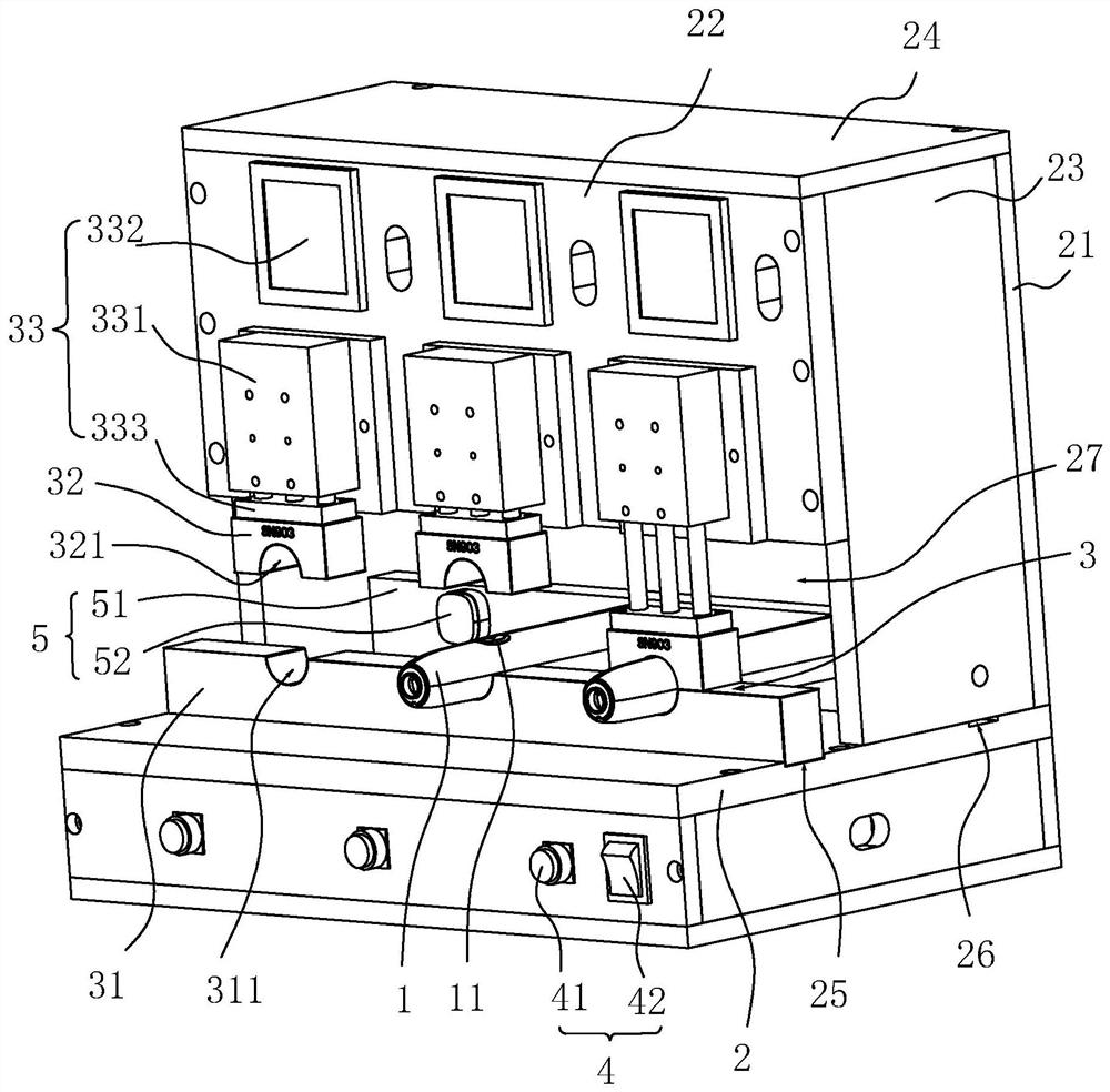
[0054] refer to figure 1 , the pressure maintaining equipment includes a workbench 2 , a pressing mechanism 3 , a control mechanism 4 and a positioning mechanism 5 .

[0055] refer to figure 1 , The workbench 2 is provided with a rear baffle 21 , a control front plate 22 , a side plate 23 and a top plate 24 . There are two side panels 23 , which are detachably located on opposite sides between the rear baffle 21 and the control front panel 22 respectively. The top panel 24 is installed on the rear baffle 21 , the control front panel 22 and the side panels 23 . There are pressure block installation grooves 25 and positioning installation grooves 26 on the worktable 2; On one side, an operation port 27 is provided between the control front plate 22 and the workbench 2 .

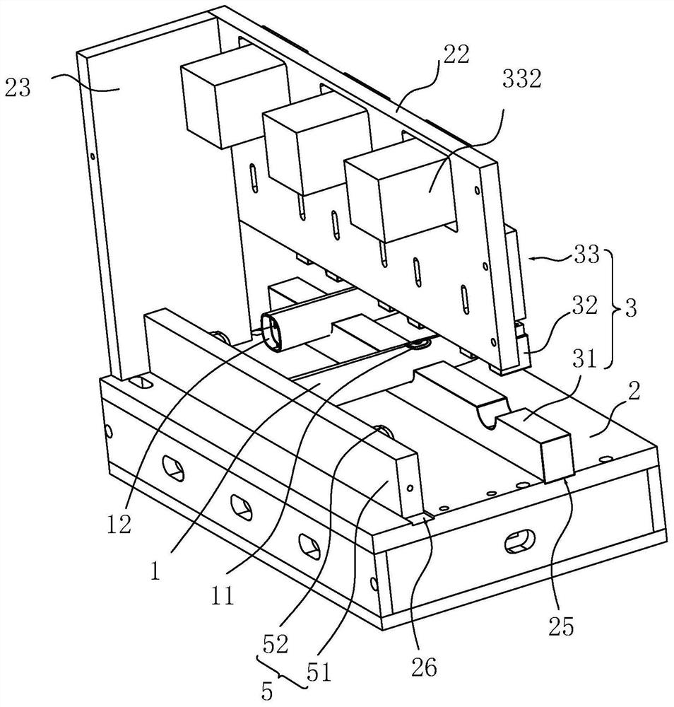
[0056] refer to figure 2 , the pressing mechanism 3 includes a lower pressing block 31 , an upper pressing block...

Embodiment 2

[0072] This embodiment discloses a pressure maintaining device.

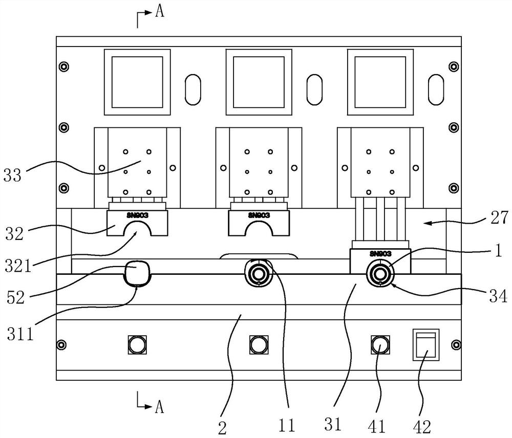
[0073] refer to Figure 4 , the difference between the pressure maintaining device in this embodiment and the first embodiment is that the inner diameter of the concave through groove 311 gradually decreases from the side close to the positioning seat 51 to the other side, forming a matching part with the button 11 of the brush handle 1 The inclined surface makes the inner diameter of the pressing ring groove 34 gradually decrease from one end close to the positioning mechanism 5 to the other end. Because the brush handle 1 is a tubular structure made of injection molding, it has a certain amount of elastic deformation, so that the brush handle 1 can be matched and installed between the lower concave through groove 311 and the positioning block 52, and the upper pressing block 32 acts on the brush handle 1. The button 11 of the device can be evenly applied and pressed, which can effectively improve the problems...


PUM


Abstract

The application relates to a pressure maintaining device and a key pressure maintaining method. The pressure maintaining equipment includes a workbench and a pressing mechanism, a control mechanism and a positioning mechanism installed on the workbench. The pressing mechanism including the upper pressing block and the lower pressing block is used to press and maintain the pressure on the buttons set on the brush handle, which can effectively improve the uniform force of the buttons and can improve the problem that the keys are lifted and detached from the brush handle during use; the upper pressing block and the lower pressing block The movement of the briquetting blocks towards or away from each other is controlled by the moving components, reducing manual manipulation, making the holding pressure uniform and improving the holding efficiency. The button pressure maintaining method includes steps such as preset pressure maintaining time, pressure maintaining operation, and removal of the brush handle. The preset pressure maintaining time is adopted, and the pressure maintaining device is used to maintain pressure on the keys of the brush handle, so that the keys of the brush handle can be unified and It is evenly installed on the brush handle, which can effectively improve problems such as key tilting.

Description

technical field [0001] The present application relates to a pressure maintaining device and a button pressure maintaining method. Background technique [0002] The electric toothbrush is an oral cleaning appliance that makes the brush head generate high-frequency vibration through the rapid rotation or vibration of the motor core, instantly decomposes the toothpaste into fine foam, and deeply cleans the gap between the teeth. The control buttons for controlling the electric toothbrush are generally arranged on the brush handle, and when in use, the electric toothbrush can be controlled by contacting and pressing the control buttons. [0003] At present, electric toothbrushes are mostly assembled manually. When installing the buttons of the brush handle, first apply glue to the part where the buttons are installed on the brush handle, and then press the button to install it on the brush handle. It needs to be maintained for a period of time (i.e., the pressure is maintained)...

Claims


Application Information

Patent Timeline
Patent Type & Authority Patents(China)
IPC IPC(8): A61C17/22A61C17/34H01H11/00
CPCA61C17/3481A61C17/225H01H11/00
Inventor 袁帅何华杰何明峰刘青云
Owner SHENZHEN BAOLIJIE TECH CO LTD
Why Eureka
Try Eureka