Novel hydraulic breaker oil way with function of preventing piston from being stuck

A technology of hydraulic crushing and hydraulic oil, which is used in mechanically driven excavators/dredgers, earthmoving machines/shovels, construction, etc. Body hole and piston hydraulic clamping force and friction force, etc., to reduce hydraulic clamping force and friction force, improve production efficiency, and solve the effect of locking and straining

Inactive Publication Date: 2021-04-30
JIANGSU LIBOSHI MACHINERY
View PDF6 Cites 0 Cited by
  • Summary
  • Abstract
  • Description
  • Claims
  • Application Information

AI Technical Summary

Problems solved by technology

[0003] During the working process of the hydraulic breaker, when the piston travels in the middle cylinder, the high-pressure hydraulic oil is input from the bias direction, resulting in a bias pressure on the piston, and the piston cannot be located in the axially symmetrical space of the middle cylinder during the reciprocating movement. On the other hand, it forms the deflection friction force of the piston against the inner hole of the middle cylinder, destroys the oil film between the middle cylinder hole and the piston, and increases the hydraulic clamping force and friction force between the middle cylinder hole and the piston, thus making it easy for the piston to Locked and strained with the middle cylinder, causing damage to the equipment and affecting production

Method used


Image

  • Novel hydraulic breaker oil way with function of preventing piston from being stuck
  • Novel hydraulic breaker oil way with function of preventing piston from being stuck
  • Novel hydraulic breaker oil way with function of preventing piston from being stuck

Examples


Embodiment Construction

[0016] refer to Figure 1 to Figure 3 A further description will be given to an embodiment of the oil circuit of a novel hydraulic breaker with anti-piston stuck in the present invention.

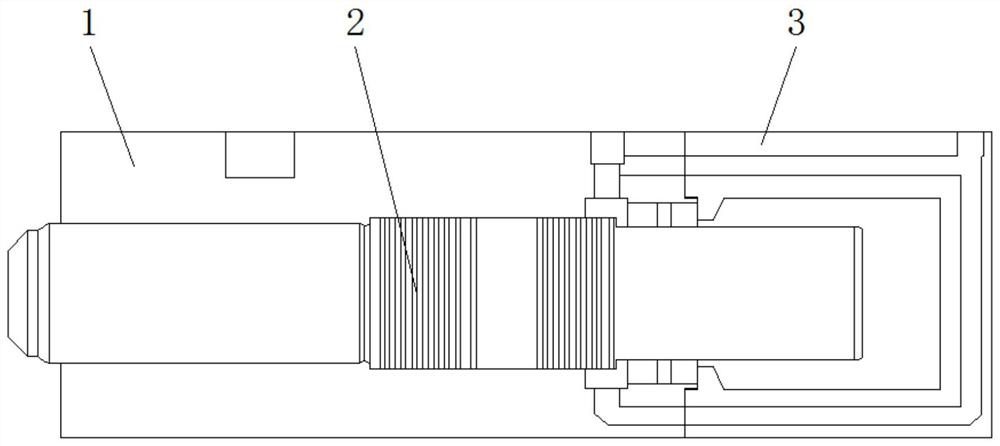
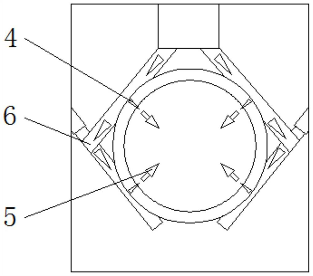
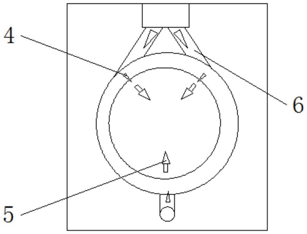
[0017] A new hydraulic breaker oil circuit with anti-piston stuck, see figure 1 and 2 , comprising a middle cylinder 1 and a rear cylinder 3, the middle cylinder 1 and the rear cylinder 3 are fixedly connected, and the inside of the middle cylinder 1 is provided with a piston 2, the piston 2 passes through the rear cylinder 3, and the inside of the middle cylinder 1 All are provided with an oil passage 6, and the hydraulic oil in the internal oil passage 6 of the middle cylinder 1 flows into the inside of the middle cylinder 1 from the middle cylinder hole provided on the middle cylinder 1 along a plurality of symmetrical directions. The hydraulic oil in the oil circuit 6 is input or output from multiple symmetrical directions, so that the force on the periphery of the piston 2 is uniform...


PUM


Abstract

The invention discloses a novel hydraulic breaker oil way with the function of preventing a piston from being stuck, and relates to the technical field of hydraulic breaker oil ways. According to the technical scheme, the novel hydraulic breaker oil way is characterized by comprising a middle cylinder body and a rear cylinder body, the middle cylinder body is fixedly connected with the rear cylinder body, the piston is arranged in the middle cylinder body, the piston penetrates through the rear cylinder body, an oil way is arranged in the middle cylinder body, and hydraulic oil in the oil way in the middle cylinder body flows into the middle cylinder body from a middle cylinder hole formed in the middle cylinder body in multiple symmetrical directions; and the novel hydraulic breaker oil way has the the effects that oil ways are arranged in the middle cylinder body and the rear cylinder body, the hydraulic oil in the oil ways is input into the middle cylinder body and the rear cylinder body in the multiple symmetrical directions, so that the periphery of the piston is stressed uniformly, uniform centripetal pressure is formed, it is guaranteed that the piston is positioned at an axis symmetric space position in the middle cylinder hole, a uniform circumferential oil film is formed, and therefore the piston easily does reciprocating motion in the oil film, hydraulic clamping force and friction force are reduced, and the phenomena of locking and pulling damage of the piston and the middle cylinder hole are solved.

Description

technical field [0001] The invention relates to the technical field of hydraulic breaker oil circuit, more specifically, it relates to a novel hydraulic breaker oil circuit with anti-piston jamming. Background technique [0002] The power source of the hydraulic breaker is the pressure provided by the excavator, loader or pump station, which can more effectively break stones and rocks in engineering construction and improve work efficiency. [0003] During the working process of the hydraulic breaker, when the piston travels in the middle cylinder, the high-pressure hydraulic oil is input from the bias direction, resulting in a bias pressure on the piston, and the piston cannot be located in the axially symmetrical space of the middle cylinder during the reciprocating movement. On the other hand, it forms the deflection friction force of the piston against the inner hole of the middle cylinder, destroys the oil film between the middle cylinder hole and the piston, and increa...

Claims


Application Information

Patent Timeline
IPC IPC(8): E02F3/96
CPCE02F3/96E02F3/966
Inventor 张春生
Owner JIANGSU LIBOSHI MACHINERY
Why Eureka
Try Eureka