Loading bin structure for heat pipe feeding, heat pipe rod pulling device and rod pulling method

A heat pipe and silo technology, applied in the field of heat pipe production equipment, can solve the problems of large resistance, difficult to pull out, high defect rate, time-consuming and labor-intensive, etc., and achieve the effect of saving labor costs.

Active Publication Date: 2021-06-18
太仓市华盈电子材料有限公司
View PDF0 Cites 0 Cited by
  • Summary
  • Abstract
  • Description
  • Claims
  • Application Information

AI Technical Summary

Problems solved by technology

[0003] The preparation of the heat pipe is generally made by sintering a layer of metal outside the mandrel. After the sintering is completed, the center rod, that is, the mandrel, is pulled out to make the heat pipe. The existing heat pipe loading and unloading usually uses It is time-consuming and labor-intensive to pull out one by one manually. When the central rod is bent and deformed or the surface is rough, the resistance is high and it is difficult to pull out, and the defective rate is high.

Method used


Image

  • Loading bin structure for heat pipe feeding, heat pipe rod pulling device and rod pulling method
  • Loading bin structure for heat pipe feeding, heat pipe rod pulling device and rod pulling method
  • Loading bin structure for heat pipe feeding, heat pipe rod pulling device and rod pulling method

Examples


Embodiment Construction

[0047] The present invention will be described in detail below in conjunction with various embodiments shown in the drawings. However, these embodiments do not limit the present invention, and structural, method, or functional changes made by those skilled in the art according to these embodiments are included in the protection scope of the present invention.

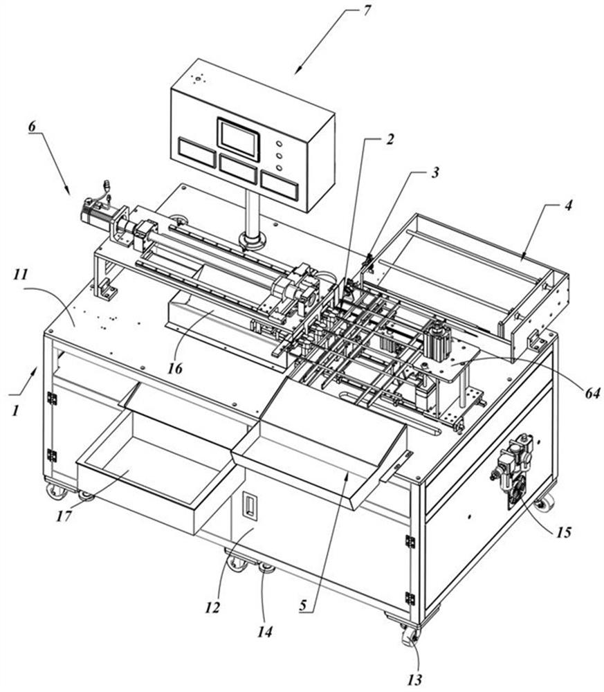
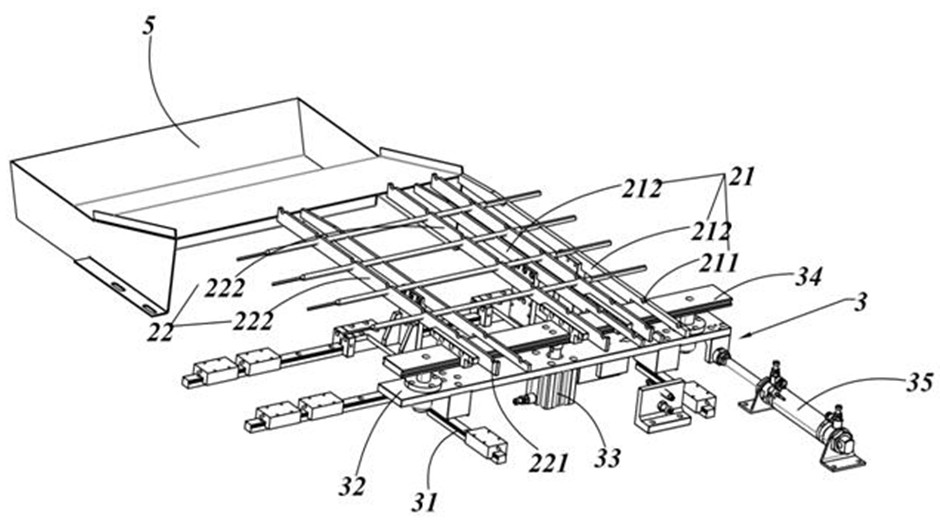
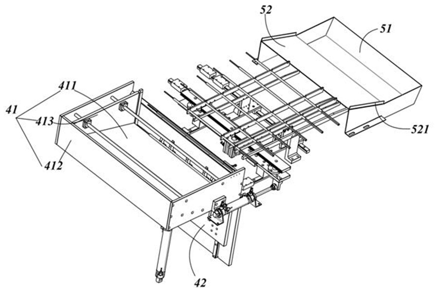
[0048] refer to figure 1 and figure 2 As shown, an embodiment of the present application provides an automatic rod pulling device for heat pipes, including a base 1, a heat pipe carrying assembly 2, an upper bin structure 4, a receiving bin structure 5, and a heat pipe rod pulling assembly 6; the heat pipe carrying assembly 2 It includes the first rail group 21 and the second rail group 22 arranged in the same direction, the first rail group 21 is fixedly arranged on the base 1, the second rail group 22 is movably arranged on the base 1 and connected to the drive assembly 3, the second The rail group 22 includes a dr...


PUM


Abstract

The invention discloses a feeding bin structure for heat pipe feeding, which includes a feeding bin body, a material jacking cylinder and a rod fetching structure. From the root to the top, the rod-taking structure includes several first rod-taking units and second rod-taking units. The top of each first rod-taking unit is recessed with a first groove, and two limiting protrusions on both sides of the first groove The protruding height is not greater than the radius of the heat pipe to be ejected; the top of each second rod-taking unit is recessed with a second groove, and a first limiting part extends from one side of the second groove. The height protruding from the bottom of the second groove is greater than the radius of the heat pipe to be ejected, and the other side of the second groove extends a second limiting part, and the height of the second limiting part protruding from the bottom of the second groove is smaller than the radius of the heat pipe to be ejected. The radius of the ejected heat pipe. By limiting the protruding height of at least one of the two limiting protrusions to be no greater than the radius of the heat pipe to be ejected, only one heat pipe can exist in the groove at each ejection.

Description

technical field [0001] The invention belongs to the technical field of heat pipe production equipment, and in particular relates to a feeding bin structure for heat pipe feeding, a heat pipe rod pulling device and a rod pulling method. Background technique [0002] The heat pipe is a special material with rapid temperature uniformity. Its hollow metal pipe body makes it light in weight, and its rapid temperature uniformity makes it have excellent thermal superconductivity. The application of heat pipe The scope is quite wide. It was first used in the aerospace field, and it has been widely used in various heat exchangers, coolers, natural geothermal energy, etc., and plays the role of rapid heat conduction. It is the most common and efficient heat conduction in today's electronic product cooling devices. (non-heat sinking) components. [0003] The preparation of the heat pipe is generally made by sintering a layer of metal outside the mandrel. After the sintering is complet...

Claims


Application Information

Patent Timeline
Patent Type & Authority Patents(China)
IPC IPC(8): B22F3/00B22F3/10B22F5/10
CPCB22F3/003B22F3/005B22F3/10B22F5/106B22F2003/1046B22F2005/103
Inventor 刘爱标
Owner 太仓市华盈电子材料有限公司
Why Eureka
Try Eureka