A fuel cell hydrogen injector refrigerant temperature difference flow monitoring device
A fuel cell and flow monitoring technology, which is applied to fuel cells, electrical components, electrochemical generators, etc., can solve the problems of poor installation and fixation effect of the ejector and high temperature, and achieves improved shock absorption effect, convenient operation and simple use. Effect
- Summary
- Abstract
- Description
- Claims
- Application Information
AI Technical Summary
Problems solved by technology
Method used
Image

Examples
Embodiment 1
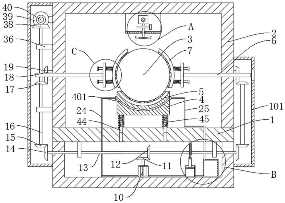
[0035] refer to figure 1 , figure 2 , image 3 , Figure 4 , Figure 8 , a fuel cell hydrogen ejector refrigerant temperature difference flow monitoring device, including a support base 1, a support frame 2, an ejector body 3 and a liquid cooling mechanism, the support frame 2 is fixedly connected to the support base 1, and the support base 1 slides on A base 4 is connected, an arc-shaped card slot 5 is fixedly connected to the base 4, the ejector body 3 is placed on the arc-shaped card slot 5, and a cooling groove 401 is opened on the base 4, and the cooling groove 401 is connected with the liquid cooling mechanism, The support frame 2 is slidably connected with a threaded rod 6, and the threaded rod 6 is fixedly connected with an arc-shaped clip seat 7, which is in contact with the ejector body 3. The support frame 2 is rotatably connected with a rotating shaft 8, and on the rotating shaft 8 A cooling fan 9 is fixedly connected, and a driving mechanism is fixedly connec...
Embodiment 2
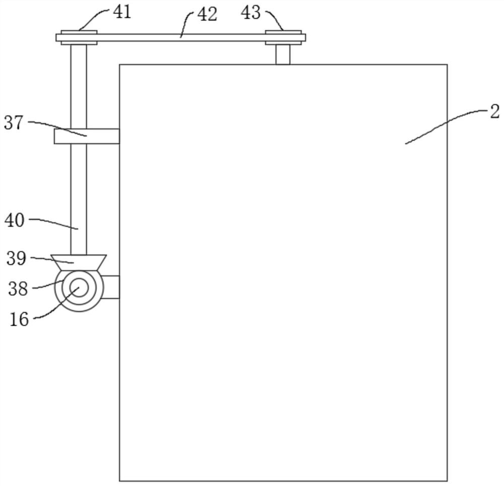
[0047] refer to figure 1 , Figure 5 , Figure 9 , a fuel cell hydrogen ejector refrigerant temperature difference flow monitoring device, including a support base 1, a support frame 2, an ejector body 3 and a liquid cooling mechanism, the support frame 2 is fixedly connected to the support base 1, and the support base 1 slides on A base 4 is connected, an arc-shaped card slot 5 is fixedly connected to the base 4, the ejector body 3 is placed on the arc-shaped card slot 5, and a cooling groove 401 is opened on the base 4, and the cooling groove 401 is connected with the liquid cooling mechanism, The support frame 2 is slidably connected with a threaded rod 6, and the threaded rod 6 is fixedly connected with an arc-shaped clip seat 7, which is in contact with the ejector body 3. The support frame 2 is rotatably connected with a rotating shaft 8, and on the rotating shaft 8 A cooling fan 9 is fixedly connected, and a driving mechanism is fixedly connected to the support base 1...
Embodiment 3
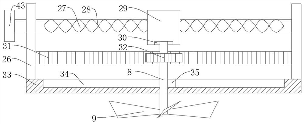
[0059] refer to figure 1 , Image 6 , Figure 7 , Figure 10 , a fuel cell hydrogen ejector refrigerant temperature difference flow monitoring device, including a support base 1, a support frame 2, an ejector body 3 and a liquid cooling mechanism, the support frame 2 is fixedly connected to the support base 1, and the support base 1 slides on A base 4 is connected, an arc-shaped card slot 5 is fixedly connected to the base 4, the ejector body 3 is placed on the arc-shaped card slot 5, and a cooling groove 401 is opened on the base 4, and the cooling groove 401 is connected with the liquid cooling mechanism, The support frame 2 is slidably connected with a threaded rod 6, and the threaded rod 6 is fixedly connected with an arc-shaped clip seat 7, which is in contact with the ejector body 3. The support frame 2 is rotatably connected with a rotating shaft 8, and on the rotating shaft 8 A cooling fan 9 is fixedly connected, and a driving mechanism is fixedly connected to the s...
PUM
 Abstract
Description
Claims
Application Information
 - R&D
- Intellectual Property
- Life Sciences
- Materials
- Tech Scout
- Unparalleled Data Quality
- Higher Quality Content
- 60% Fewer Hallucinations
Browse by: Latest US Patents, China's latest patents, Technical Efficacy Thesaurus, Application Domain, Technology Topic, Popular Technical Reports.
© 2025 PatSnap. All rights reserved.Legal|Privacy policy|Modern Slavery Act Transparency Statement|Sitemap|About US| Contact US: help@patsnap.com