
Antenna array structure, antenna and base station

An antenna array and antenna technology, which is applied to antenna arrays, antennas, and devices that enable antennas to work in different bands at the same time, can solve the problems of frequency band index deterioration, mutual coupling and reflection increase, and array space reuse rate reduction.

Pending Publication Date: 2021-05-11
COMBA TELECOM TECH (GUANGZHOU) CO LTD +1
View PDF0 Cites 0 Cited by
  • Summary
  • Abstract
  • Description
  • Claims
  • Application Information

AI Technical Summary

Problems solved by technology

However, a larger radiating unit will not only reduce the spatial multiplexing rate between arrays in the traditional layout scheme, but also require a wider backplane boundary adjustment. The low-frequency radiating unit should not be too close to the edge of the backplane, otherwise it will inevitably lead to low-frequency and other frequency bands. The projections of the radiation units interfere with each other, the maximum radiation directions are mutually blocked, and the mutual coupling and reflection between the frequency bands increase sharply, which makes the indicators of each frequency band deteriorate rapidly, seriously affects the system performance, and cannot meet the use requirements

Method used


Image

  • Antenna array structure, antenna and base station
  • Antenna array structure, antenna and base station
  • Antenna array structure, antenna and base station

Examples


Embodiment Construction

[0032] Embodiments of the present invention are described in detail below, examples of which are shown in the drawings, wherein the same or similar reference numerals denote the same or similar elements or elements having the same or similar functions throughout. The embodiments described below by referring to the figures are examples, and are only for explaining the present invention and should not be construed as limiting the present invention.

[0033] Those skilled in the art will understand that unless otherwise stated, the singular forms "a", "an", "said" and "the" used herein may also include plural forms. It should be further understood that the word "comprising" used in the description of the present invention refers to the presence of said features, integers, steps, operations, elements and / or components, but does not exclude the presence or addition of one or more other features, integers, steps, operations, elements and / or components, but does not preclude the pres...


PUM


Abstract

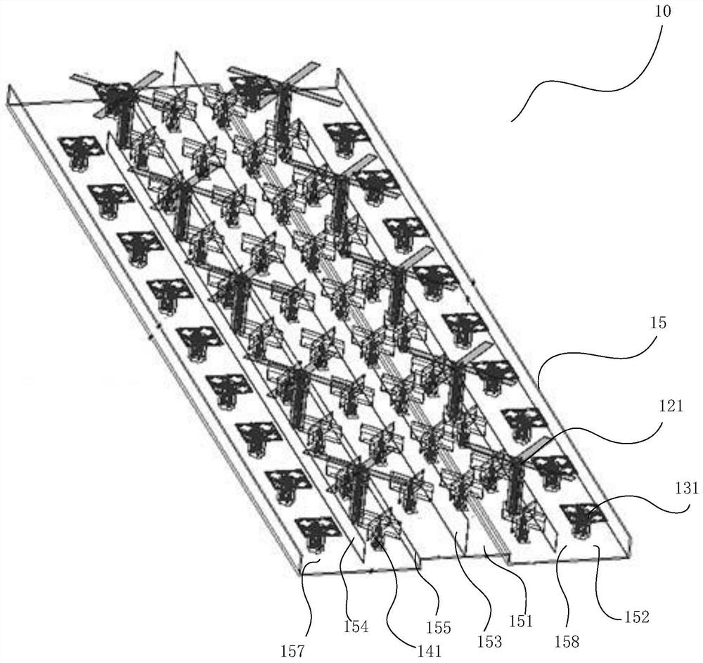
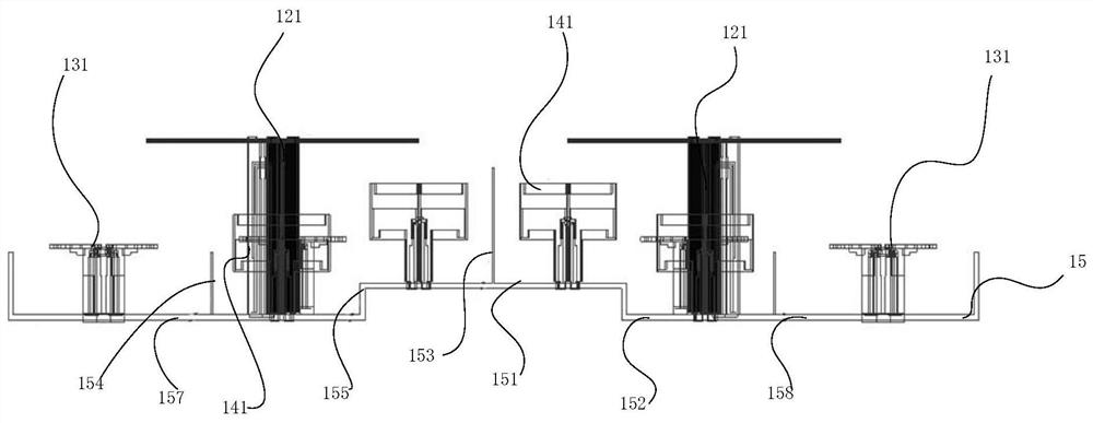
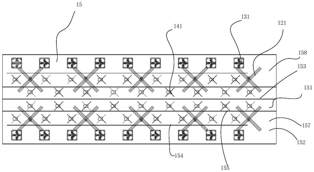
The invention provides an antenna array structure, an antenna and a base station, the antenna array structure comprises a low-frequency array, an intermediate-frequency array and a high-frequency array which are arranged on the same reflecting plate, each array comprises a plurality of radiation units which are linearly arranged and correspond to the frequency bands of the radiation units, and in the transverse direction of the reflecting plate, the multiple high-frequency arrays are arranged side by side in the middle, the two low-frequency arrays and the two high-frequency arrays on the side edges of the low-frequency arrays are arranged in a collinear mode, and the two intermediate-frequency arrays are arranged outside the high-frequency arrays on the side edges; in the transverse direction of the reflecting plate, the reflecting plate is provided with a highest supporting face in the middle and non-highest supporting faces symmetrically distributed on the two sides of the highest supporting face, and the high-frequency array between the two columns which are arranged in the collinear mode is arranged on the highest supporting face. According to the invention, a plurality of arrays with different frequency bands are arranged on the highest supporting surface and the non-highest supporting surface by adopting a spatial multiplexing technology, the arrays do not interfere with each other, and the radiation performance is better.

Description

technical field [0001] The invention belongs to the technical field of mobile communication, and in particular relates to an antenna array structure, an antenna configured with the antenna array structure, and a base station configured with the antenna. Background technique [0002] TDD antennas are often referred to as smart antennas, which consist of several sub-arrays that can be adapted to add weights to accurately track multiple mobile devices. The smart antenna has the symmetry of uplink and downlink, which can effectively reduce multipath interference and improve the reliability of the communication system and the efficiency of spectrum use. Based on the above advantages, smart antennas are widely used and promoted in the industry. At the same time, the smart antenna needs to receive the precise amplitude and phase of each sub-array in order to accurately locate the mobile device and form the broadcast beam. Generally speaking, in the design, each sub-array must be ...

Claims


Application Information

Patent Timeline
Patent Type & Authority Applications(China)
IPC IPC(8): H01Q21/00H01Q5/28
CPCH01Q21/00H01Q5/28
Inventor 黄文铿叶鸿桂姜维维邵金华李长恒
Owner COMBA TELECOM TECH (GUANGZHOU) CO LTD
Features
  • Generate Ideas
  • Intellectual Property
  • Life Sciences
  • Materials
  • Tech Scout
  • Unparalleled Data Quality
  • Higher Quality Content
  • 60% Fewer Hallucinations
Learn More