
Pressure relief device

A pressure relief device and pressure relief technology, which is applied in the direction of valve devices, batteries, structural parts, etc., can solve problems that affect the use of battery packs and increase the pressure of battery packs

Pending Publication Date: 2021-05-18
ILLINOIS TOOL WORKS INC
View PDF0 Cites 1 Cited by
  • Summary
  • Abstract
  • Description
  • Claims
  • Application Information

AI Technical Summary

Problems solved by technology

[0002] The battery will generate gas during use. If the gas is not discharged in time and accumulates in the battery pack, the pressure inside the battery pack will increase, which will affect the use of the battery pack.

Method used


Image

  • Pressure relief device
  • Pressure relief device
  • Pressure relief device

Examples


Embodiment Construction

[0026] Various embodiments of the present application will be described below with reference to the accompanying drawings, which form a part hereof. It should be understood that although directional terms, such as "front," "rear," "upper," "lower," "left," "right," etc., are used throughout this application to describe various exemplary structural parts of this application and elements, but these terms are used herein for explanatory purposes only, based on the example orientations shown in the figures. Since the embodiments disclosed in this application can be arranged in different orientations, these directional terms are for illustration only and should not be regarded as limiting. Where possible, the same or similar reference numerals are used in this application to refer to the same components.

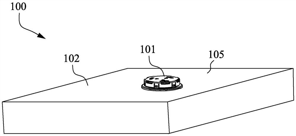
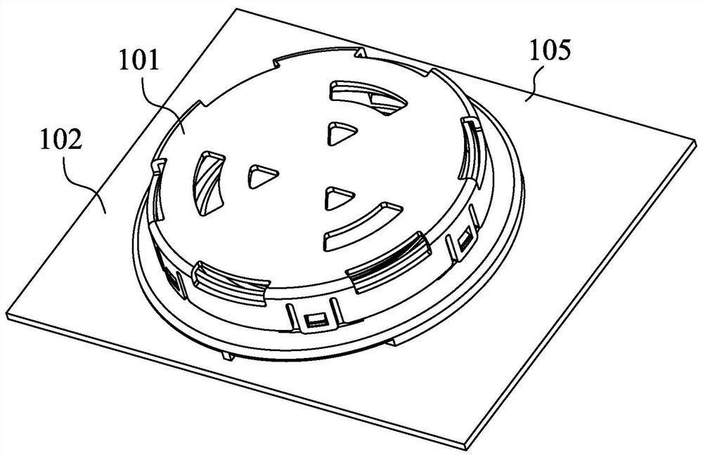
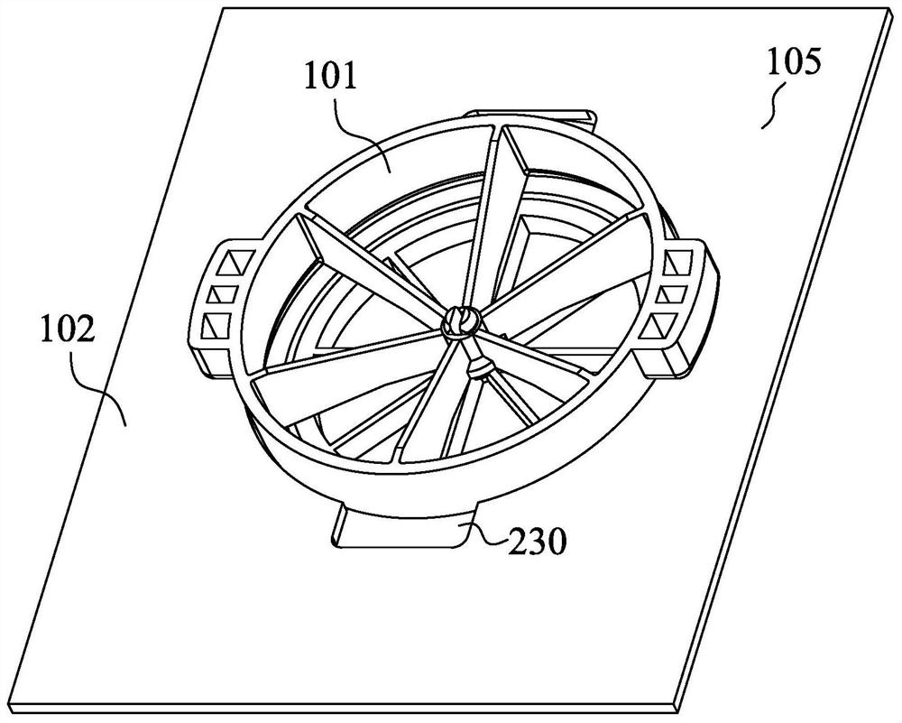
[0027] figure 1 A schematic diagram of a battery pack 100 using a pressure relief device 101 according to an embodiment of the present application is shown. As shown in FIG. 1...


PUM


Abstract

A pressure relief device (101), comprising a mounting seat (3505), a valve core (3504) and a pressure relief member (3502), a fluid channel (3401) being provided inside the mounting seat (3505), the fluid channel (3401) being capable of communicating with an internal space of a component to be subjected to pressure relief; the valve core (3504) is arranged in the mounting seat (3505) and is aligned with the fluid channel (3401), and a pressure relief channel (3402) is formed between the outer edge of the valve core (3504) and the inner wall of the fluid channel (3401) of the mounting seat (3505); and the pressure relief member (3502) is arranged on the outer edge of the valve element (3504) in a sleeving mode, and the pressure relief member (3502) is deformable and is configured to open and close the pressure relief channel (3402) through deformation of the pressure relief member (3502). The pressure relief device (101) of the present application utilizes the deformable performance of the pressure relief member to achieve the function of repeated use and multiple pressure relief of the pressure relief device.

Description

technical field [0001] The present application relates to a pressure relief device, in particular, to a pressure relief device used in a battery pack. Background technique [0002] The battery will generate gas during use. If the gas is not discharged in time and accumulates in the battery pack, the pressure inside the battery pack will increase, which will affect the use of the battery pack. Therefore, in the manufacturing process of the battery, it is often necessary to install a pressure relief device on the battery pack. When the pressure in the battery pack is higher than the predetermined value, the pressure relief device can be automatically opened to discharge the gas accumulated inside the battery pack and reduce the excessive pressure therein. Contents of the invention [0003] The application provides a pressure relief device. The pressure relief device includes a mounting seat, a valve core and a pressure relief member. A fluid channel is provided inside the m...

Claims


Application Information

Patent Timeline
IPC IPC(8): H01M50/325F16K17/164
CPCF16K17/164F16K17/02Y02E60/10H01M50/325H01M50/394H01M50/20H01M2200/20H01M2220/20
Inventor 乐国锋滕启红
Owner ILLINOIS TOOL WORKS INC
Learn More