Electrical connector with biased latch

A technology of electrical connectors and mating connectors, applied in the direction of connection, parts of connection devices, connection/disconnection of connection devices, etc.

Pending Publication Date: 2021-05-18
ティーイーコネクティビティサービシーズゲーエムベーハー
View PDF0 Cites 0 Cited by
  • Summary
  • Abstract
  • Description
  • Claims
  • Application Information

AI Technical Summary

Problems solved by technology

While in many cases movement between connectors is harmless, in other cases (e.g. those with very tight tolerances) it is unacceptable

Method used


Image

  • Electrical connector with biased latch
  • Electrical connector with biased latch
  • Electrical connector with biased latch

Examples


Embodiment Construction

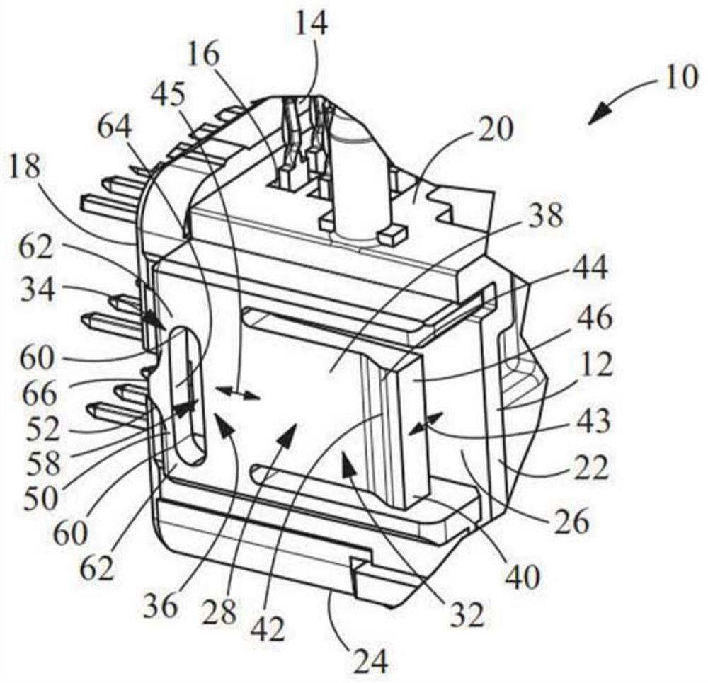
[0015] Such as figure 1 As shown, the electrical connector 10 has a housing 12 with terminals 14 positioned in terminal receiving cavities 16 . The specific configuration and number of terminals 14 and terminal receiving cavities 16 may vary without departing from the scope of the present invention. Housing 12 has a first wall or mating face 18 , a circuit board receiving face 20 , a second or rear wall 22 , a bottom wall 24 and side walls 26 .

[0016] exist figure 1 In the illustrative embodiment shown, the latch 28 extends from proximate the first wall 18 of the housing 12 to proximate the second wall 22 . Such as Figure 6 and 8 As shown, the latch 28 has an attachment portion 30 that attaches the latch 28 to the side wall 26 of the housing 12 . The latch 28 has a latching region or end 32 and an oppositely facing biasing region or end 34 . A transition region or portion 36 extends between the latch region or end 32 and the biasing region or end 34 .

[0017] The la...


PUM


Abstract

The present invention relates to an electrical connector (10) with a biasing latch (28) and a method. The electrical connector (10) has a housing (12) and a latch (28) extending from the housing (12). The latch (28) has a latch region (32) and a biasing region (34). The latching region (32) has a latching projection (42) with a reference surface (46). The biasing region (34) has a biasing member (50). Mating of the biasing member (50) with the mating electrical connector (110) and mating of the reference surface (46) with the mating electrical connector (110) prevent the undesired movement of the electrical connector (10) relative to the mating electrical connector (110).

Description

technical field [0001] The present invention relates to an electrical connector having a latch having a biasing member. In particular, the present invention is directed to a latch having a biasing member that holds the latch and connector in place to minimize the effects of manufacturing tolerances. Background technique [0002] When the electrical connector is assembled to a mating electrical connector or panel, one or more spring beams or latches are used to secure the components together. When the electrical connectors are mated, the spring beam deflects and moves past the mating surface of the mating beam. To facilitate the movement of a flexible beam, the beam must be allowed to move past or over mating surfaces to allow the beam to move back in the unstressed direction. Thus, when the connectors are mated, the electrical connector has some movement or play relative to the mating connector. While in many cases connector-to-connector movement is harmless, in other cas...

Claims


Application Information

Patent Timeline
Patent Type & Authority Applications(China)
IPC IPC(8): H01R13/639
CPCH01R13/639H01R12/724H01R13/743H01R13/627H01R13/6271H01R13/6272H01R13/629H01R43/26
Inventor H.C.莫尔E.J.托里
Owner ティーイーコネクティビティサービシーズゲーエムベーハー
Why Eureka
Try Eureka