
Valve rod assembly, high-pressure fuel injection valve and engine electronic control fuel injection system

A component and valve rod technology, which is applied in the field of engine electronically controlled fuel injection system, can solve problems such as slowing down the opening speed of the piston rod or valve needle, and speeding up the closing speed of the piston rod or valve needle, so as to control bad combustion and improve pre-injection effect, the effect of reducing specific gravity

Pending Publication Date: 2021-06-04
钧风电控科技泰州有限责任公司
View PDF0 Cites 0 Cited by
  • Summary
  • Abstract
  • Description
  • Claims
  • Application Information

AI Technical Summary

Problems solved by technology

[0003] The purpose of the embodiments of the present invention is a valve stem assembly, a high-pressure fuel injection valve and an engine electronically controlled fuel injection system to solve the technical problems of slowing down the opening speed of the piston rod or valve needle and accelerating the closing speed of the piston rod or valve needle

Method used


Image

  • Valve rod assembly, high-pressure fuel injection valve and engine electronic control fuel injection system
  • Valve rod assembly, high-pressure fuel injection valve and engine electronic control fuel injection system
  • Valve rod assembly, high-pressure fuel injection valve and engine electronic control fuel injection system

Examples


Embodiment Construction

[0028] Reference will now be made in detail to the exemplary embodiments, examples of which are illustrated in the accompanying drawings. When the following description refers to the accompanying drawings, the same numerals in different drawings refer to the same or similar elements unless otherwise indicated. The implementations described in the following exemplary embodiments do not represent all implementations consistent with this application. Rather, they are merely examples of apparatuses and methods consistent with aspects of the present application as recited in the appended claims.

[0029] The terminology used in this application is for the purpose of describing particular embodiments only, and is not intended to limit the application. As used in this application and the appended claims, the singular forms "a", "the", and "the" are intended to include the plural forms as well, unless the context clearly dictates otherwise. It should also be understood that the term...


PUM


Abstract

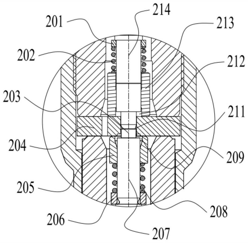
The invention relates to the technical field of high-pressure fuel injection valves, and discloses a valve rod assembly. The valve rod assembly comprises a control rod, an upper adjusting ring, an upper reset spring, an upper sleeve, a valve plate, an adjusting pad, a lower sleeve, a lower reset spring, a lower adjusting ring and a valve needle, the upper adjusting ring, the upper reset spring and the upper sleeve are connected to the control rod in a sleeved manner in sequence from top to bottom, the lower sleeve, the lower reset spring and the lower adjusting ring are connected to the valve needle in a sleeved manner in sequence from top to bottom, the upper sleeve and the lower sleeve are respectively abutted against the upper end surface and the lower end surface of the valve plate, the upper surface and the lower surface of an adjusting pad are respectively abutted against the control rod and the valve needle, and the valve plate is provided with one or more channels used for fuel circulation and throttling. The invention further discloses a high-pressure fuel injection valve which comprises the valve rod assembly. The invention also discloses an engine electronic control fuel injection system which comprises the high-pressure fuel injection valve. The technical problems that the opening speed of the control rod or the valve needle is decreased, and the closing speed of the control rod or the valve needle is increased are solved.

Description

technical field [0001] The invention relates to the technical field of high-pressure fuel injection valves, in particular to a valve stem assembly, a high-pressure fuel injection valve and an electronically controlled fuel injection system for an engine. Background technique [0002] In today's world, the emission of powertrain pollutants has become the focus of attention of the international community. With the increasingly stringent emission regulations, the electronically controlled fuel injection system for engines that can realize high-pressure and precise control of injection has become the only technical route for diesel engine technology. In order to achieve effective control of pollutant emissions, it is necessary to precisely control the opening and closing of the injection process, so that the injection waveform reaches the state of slow first and then fast, which is beneficial to the engine to form a more uniform combustible mixture, which can reduce fuel consumpt...

Claims


Application Information

Patent Timeline
Patent Type & Authority Applications(China)
IPC IPC(8): F02M63/00F02M51/06
CPCF02M63/007F02M63/0028F02M63/0029F02M51/06
Inventor 于建锋徐小松孙炳晓戴宏伟潘慧杨涛程雪媛
Owner 钧风电控科技泰州有限责任公司
Learn More