
Motor, camera device and terminal equipment

A motor and camera module technology, which is applied in the field of motors, camera devices and terminal equipment, can solve the problems that affect the quality and stability of images captured by terminal equipment

Active Publication Date: 2021-06-11
HUAWEI TECH CO LTD
View PDF11 Cites 3 Cited by
  • Summary
  • Abstract
  • Description
  • Claims
  • Application Information

AI Technical Summary

Problems solved by technology

However, it is supported by reeds or suspension wires, and the stability is not high, which affects the quality of images captured by terminal equipment

Method used


Image

  • Motor, camera device and terminal equipment
  • Motor, camera device and terminal equipment
  • Motor, camera device and terminal equipment

Examples


no. 1 approach

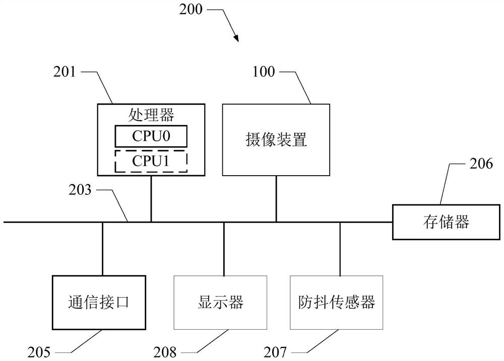
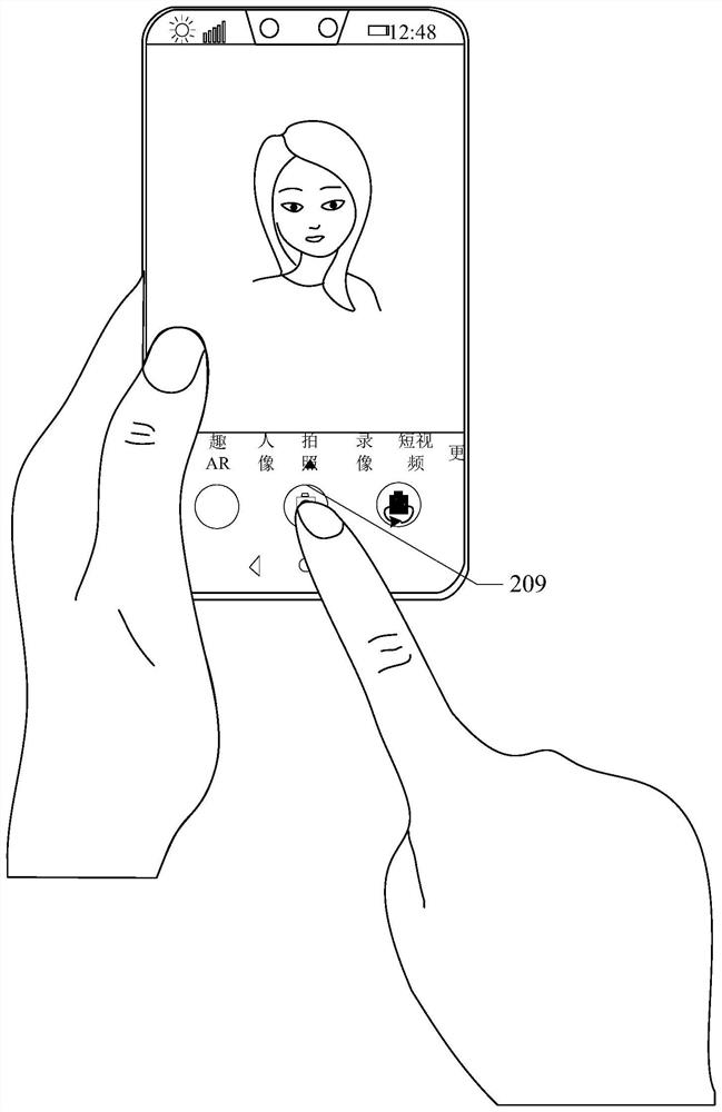
[0039] see figure 1, is a structural block diagram of a terminal device provided in the first embodiment of the present application. The terminal device 200 includes a camera 100 , a processor 201 , a communication bus 203 , at least one communication interface 205 , a memory 206 , and an anti-shake sensor 207 . The processor 201 is communicatively connected with the camera device 100 , the at least one communication interface 205 , the memory 206 , and the anti-shake sensor 207 through the communication bus 203 . The terminal device 100 may be any one of many different types of consumer electronic devices that can be easily held in the user's hand during normal use. Specifically, the terminal device 100 may be a Electronic devices, such as drones, vehicle-mounted camera equipment, smart phones, smart watches, tablet computers, personal digital assistants (personal digital assistant, PDA), notebook computers, and the like.

[0040] The processor 201 may be a central processi...

no. 2 approach

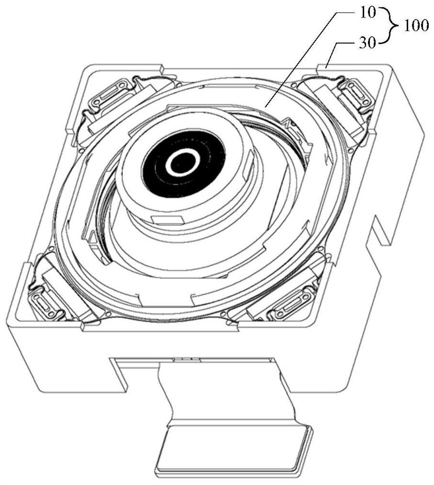
[0071] see Figure 9-Figure 10 , Figure 9 It is a three-dimensional assembly diagram of the camera device provided in the second embodiment of the present application, Figure 10 for Figure 9 The three-dimensional exploded schematic diagram of the camera device shown. The camera device 300 provided in the second embodiment of the present application has substantially the same structure as the camera device 100 provided in the first embodiment. The camera device 300 includes a camera module 50 and a motor 70 that drives the camera module 50 to achieve optical image stabilization. The difference lies in the driving method of the motor 70 of the imaging device 300 .

[0072] Specifically, see Figure 11-Figure 12 , Figure 11 for Figure 9 A three-dimensional sectional view of the camera device shown, Figure 12 for Figure 9 Another perspective cutaway view of the camera device shown. The motor 70 includes a bearing inner ring 71 , a bearing outer ring 72 , a base 73 ...


PUM


Abstract

The invention provides a motor, a camera device and terminal equipment. The motor comprises a bearing inner ring, a bearing outer ring and a driving part, the bearing inner ring is used for fixing a camera module, the bearing outer ring is arranged outside the bearing inner ring in a sleeving mode, the bearing inner ring comprises a first matching surface arranged towards the bearing outer ring, the bearing outer ring comprises a second matching surface arranged towards the first matching surface, the first matching surface and the second matching surface are spherical surfaces, and the driving part is used for driving the bearing inner ring to drive the camera module to rotate relative to the bearing outer ring, so that the shaking deviation of the camera module is compensated. As the first matching surface and the second matching surface are spherical surfaces, the stability of the camera device in the anti-shake movement process can be effectively improved through spherical surface supporting, and the quality of shot images can be improved.

Description

technical field [0001] The present application relates to the field of camera technology, in particular to a motor, camera device and terminal equipment. Background technique [0002] In terminal devices requiring high-quality images, optical image stabilization (OIS) is often used to prevent image damage caused by hand shake during shooting. Motors in traditional OIS devices are generally classified into shaft-shifting OIS motors and tilting OIS motors. Among them, the shaft-shifting OIS motor is supported by suspension wires and balls, while the inclined OIS motor is supported by reeds. However, it is supported by reeds or suspension wires, and the stability is not high, which affects the quality of images captured by the terminal equipment. Contents of the invention [0003] The technical problem to be solved by the embodiments of the present application is to provide a motor, an imaging device, and a terminal device that can improve stability. [0004] In order to a...

Claims


Application Information

Patent Timeline
Patent Type & Authority Applications(China)
IPC IPC(8): H04N5/225H04N5/232H02K41/035
CPCH02K41/0354H02K41/0356H04N23/50H04N23/6812H04N23/685
Inventor 蒋磊王建文郭利德
Owner HUAWEI TECH CO LTD
Learn More