
Roll-type coil used for camera, making method and use method of roll-type coil and coil assembly

A production method and camera technology, which is applied in the field of cameras, can solve the problems of non-disclosure and cooperation, and achieve the effect of large electromagnetic driving force, large number of coil turns, and improved optical anti-shake performance

Inactive Publication Date: 2018-12-07
TRULY OPTO ELECTRONICS
View PDF5 Cites 0 Cited by
  • Summary
  • Abstract
  • Description
  • Claims
  • Application Information

AI Technical Summary

Problems solved by technology

[0004] There are currently two known high-copper ratio coils, one is the FP coil, which uses printed circuit technology to make the coil circuit on the circuit board, and the other is the W coil, which uses integrated circuit technology to make the coil circuit Produced on silicon wafers, however, the key technologies of these two coils have always been in the hands of only a few Japanese companies, and have never been disclosed and cooperated with the public.

Method used


Image

  • Roll-type coil used for camera, making method and use method of roll-type coil and coil assembly
  • Roll-type coil used for camera, making method and use method of roll-type coil and coil assembly
  • Roll-type coil used for camera, making method and use method of roll-type coil and coil assembly

Examples


Embodiment 1

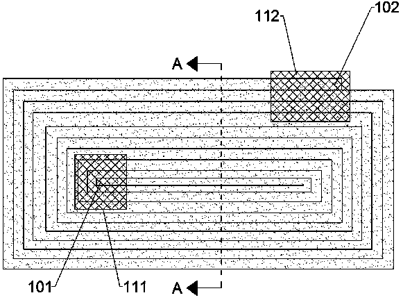
[0034] Such as image 3 with 4 As shown, a winding coil 1 for a camera is formed by coiling a conductive sheet 11 with an insulating layer on the surface to form a winding structure, and the conductive sheet 11 on one end surface is exposed as a conductive terminal.

[0035] The wound coil 1 adopts a rectangular conductive sheet 11 coiled to form a wound structure, and there is no gap between adjacent conductive sheets 11. Compared with the traditional copper wire coil, the density of the conductive material is higher, and the coil turns More numbers, greater electromagnetic driving force, especially suitable for OIS coils to improve the optical image stabilization performance of OIS motors.

[0036] In use, the conductive sheet 11 needs to be exposed from the insulating layer on one end surface of the wound coil 1 as a conductive end, and assembled with a circuit board or other connecting terminals to form an electrical connection. Such as image 3 As shown, the conductive...

Embodiment 2

[0043] Such as Figure 5 As shown, a method for manufacturing the wound coil 1 for a camera described in Embodiment 1 includes:

[0044] Step 1: Provide surface with insulating layer such as Image 6 A conductive sheet 11 shown;

[0045] This step 1 specifically includes:

[0046] Step 1.1: providing a conductive sheet 11;

[0047] In this step 1.1, the conductive sheet 11 may be a metal foil or a conductive film.

[0048] Step 1.2: making an insulating layer on the surface of the conductive sheet 11 .

[0049] In this step 1.2, the insulating layer can be insulating ink or insulating paint.

[0050]Since the wound coil 1 needs to expose the conductive sheet 11 from the insulating layer on one end surface during use as a conductive end, and assemble it with a circuit board or other connection terminals to form an electrical connection, therefore, In this step 1.2, in a specific implementation manner, when the insulating layer is made on the conductive sheet 11, the side ...

Embodiment 3

[0063] A method of using the wound coil 1 for a camera described in Embodiment 1, which is used as an OIS coil for an OIS motor.


PUM


Abstract

The invention discloses a roll-type coil used for a camera, a making method and a use method of the roll-type coil and a coil assembly. The roll-type coil is of a coil type structure formed by windinga conductive sheet with an insulation layer. The conductive sheet on one side end face is exposed to serve as a conductive end. Compared with a traditional copper wire coil, the density of conductivematerials is quite big; more the turns of the coil are provided; the electromagnetic driving force is quite big; and the coil is especially suitable for being used as an OIS coil to improve optical shaking-proof performance of an OIS motor.

Description

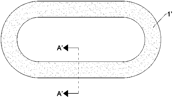
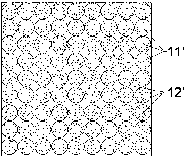
technical field [0001] The invention relates to the field of cameras, in particular to a wound coil for a camera, a manufacturing method, a usage method and a coil assembly. Background technique [0002] In the cameras of smart terminals such as mobile phones and tablets, coils are usually used to drive the lens to move to complete the focus and optical anti-shake functions. The interaction between the electromagnetic force generated by electrification and the permanent magnetic force of the magnet drives the lens to focus. In the OIS motor, in addition to the focusing coil, two OIS coils are also set on the motor base. The interaction between the electromagnetic force and the permanent magnetic force of the magnet drives the lens for optical image stabilization. [0003] With the development of camera miniaturization, the coil needs to have more turns in the same volume and resistance, so as to improve the electromagnetic driving force. However, if figure 1 with 2 As sh...

Claims


Application Information

Patent Timeline
Patent Type & Authority Applications(China)
IPC IPC(8): H02K41/035H02K15/04
CPCH02K15/04H02K41/0356
Inventor 谢荣富
Owner TRULY OPTO ELECTRONICS
Learn More