Frequency converter with reduced pre-charging time

A frequency converter and capacitor technology, applied in the field of frequency converters, can solve the problems of high cost, large overall volume, and long time support for capacitor precharging, etc.

Pending Publication Date: 2021-06-15
SIEMENS AG
View PDF1 Cites 0 Cited by
  • Summary
  • Abstract
  • Description
  • Claims
  • Application Information

AI Technical Summary

Problems solved by technology

However, the overall volume is still large due to the need for both a pre-charge circuit and a filter circuit
Therefore, the cost is still high
Also, it takes a relatively long time to precharge the support capacitors

Method used


Image

  • Frequency converter with reduced pre-charging time
  • Frequency converter with reduced pre-charging time
  • Frequency converter with reduced pre-charging time

Examples


Embodiment Construction

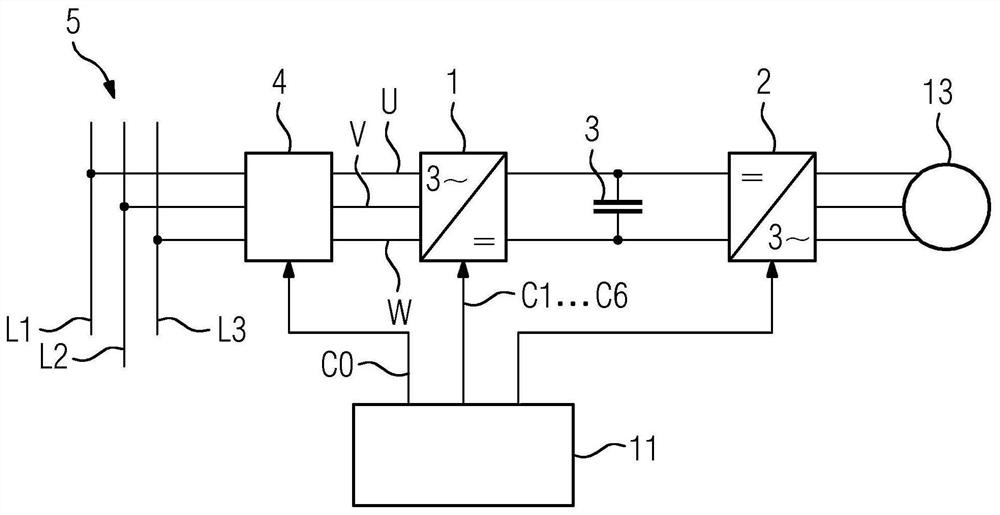
[0035] according to figure 1 , the frequency converter has a rectifier 1 on the input side. A further device 2 is arranged downstream of the rectifier 1 on the output side. The frequency converter also has at least one supporting capacitor 3 which is arranged between the rectifier 1 and the further device 2 . This further device is usually designed as an inverter. In this case it is an intermediate current converter. However, this further device can also be of a different design, for example as a direct current consumer, a direct current grid, a photovoltaic system or an energy store.

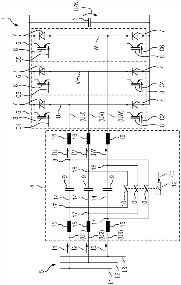
[0036] The rectifier 1 has U, V, W phases on the input side, which are connected via an upstream circuit 4 to the phases L1 , L2 , L3 of the supply network 5 . Both rectifier 1 and supply network 5 are therefore polyphase, that is to say they each have a plurality of phases U, V, W or L1 , L2 , L3 . The phases U, V, W of the rectifier 1 are referred to below as input-side phases U, V, W to...


PUM


Abstract

The invention relates to a frequency converter with a rectifier (1) on the input side and at least one support capacitor (3) arranged downstream of the rectifier (1). The rectifier (1) has multiple half-bridges (6), via which a respective input-side phase (U, V, W) of the rectifier (1) feeds the support capacitor (3). The half-bridges (6) have active switching elements (8) such that the rectifier (1) is designed as a recovery rectifier. The input-side phases (U, V, W) are connected to grid-side phases (L1, L2, L3) of a multiphase supply grid (5) via a preceeding circuit (4). Each grid-side phase (L1, L2, L3) is connected to one of the input-side phases (U, V, W) within the preceeding circuit (4) via a respective phase capacitor (9). A controller (11) of the frequency converter controls the active switching elements (8) when a first charge state (Z1) of the support capacitor (3) is reached such that input-side phase voltages (UU, UV, UW) are applied to the input-side phases (U, V, W) via the active switching elements (8), said voltages running in the opposite direction to the grid-side phase voltages (U1, U2, U3) applied to the grid-side phases (L1, L2, L3) to which the input-side phases (U, V, W) are connected via the phase capacitors (9).

Description

technical field [0001] The invention relates to a frequency converter, [0002] - wherein the frequency converter has a rectifier on the input side and at least one support capacitor arranged downstream of the rectifier, [0003] - wherein the rectifier has a plurality of half-bridges via which corresponding input-side phases of the rectifier supply the supporting capacitors, [0004] - where the half-bridge has active switching elements so that the rectifier is designed as a regenerative converter, [0005] - where the input side phase of the rectifier is connected to the grid side of the polyphase supply network via an upstream circuit, [0006] - wherein the grid-side phases are each connected within the upstream circuit to one of the input-side phases via a corresponding phase capacitor. Background technique [0007] Mains-powered frequency converters usually require a filter circuit and a pre-charging circuit between the power supply network and the rectifier on the ...

Claims


Application Information

Patent Timeline
IPC IPC(8): H02M1/36H02M5/458H02M7/12H02M7/757H02M7/758H02M1/00
CPCH02M1/36H02M5/4585H02M7/125H02M7/757H02M7/758H02M1/0064H02M7/05H02M7/062H02M7/2173H02M7/219
Inventor 亚历山大·亨斯勒菲利普·奥施曼
Owner SIEMENS AG
Why Eureka
Try Eureka