Full-automatic quick-switching device for emergency rescue engineering equipment

A technology for engineering equipment and emergency rescue, which is applied to mechanically driven excavators/dredgers, earth movers/shovels, construction, etc., and can solve problems such as high manufacturing costs and insufficient compact structure of multi-functional quick-change devices. Achieve the effects of low manufacturing cost, simple structure, and easy repair and maintenance

Active Publication Date: 2021-07-16
HUNAN UNIV
View PDF16 Cites 1 Cited by
  • Summary
  • Abstract
  • Description
  • Claims
  • Application Information

AI Technical Summary

Problems solved by technology

[0005] The purpose of this application is: to meet the rescue needs of the rapid switching of various tools and multi-degree-of-freedom composite operations in complex disaster sites, and to solve the problems of insufficient compact structure and high manufacturing cost of existing multi-functional quick-change devices, this application proposes A fully automatic quick-change device for emergency rescue engineering equipment, which realizes the quick switching of buckets, buckets, hydraulic shears, hydraulic hammers and other lower connecting attachments, as well as the flexible rotation of the lower connecting attachments around the shaft and the oil circuit Under the premise of ensuring compact structure and reducing the difficulty of manufacturing process, it can improve the ability of disaster rescue and emergency response

Method used


Image

  • Full-automatic quick-switching device for emergency rescue engineering equipment
  • Full-automatic quick-switching device for emergency rescue engineering equipment
  • Full-automatic quick-switching device for emergency rescue engineering equipment

Examples


Embodiment Construction

[0029] In order to understand the above objects, features, and advantages of the present application, the following detailed description will be made in conjunction with the accompanying drawings and specific embodiments. It should be noted that the features of the present application and the features in the embodiments and embodiments of the present application can be combined with each other.

[0030] In the following description, many specific details are set forth to fully understand the present application, but the present application can also employ other different ways to be implemented herein, and therefore, the scope of the claims are not disclosed below. Specifically, the limit is limited.

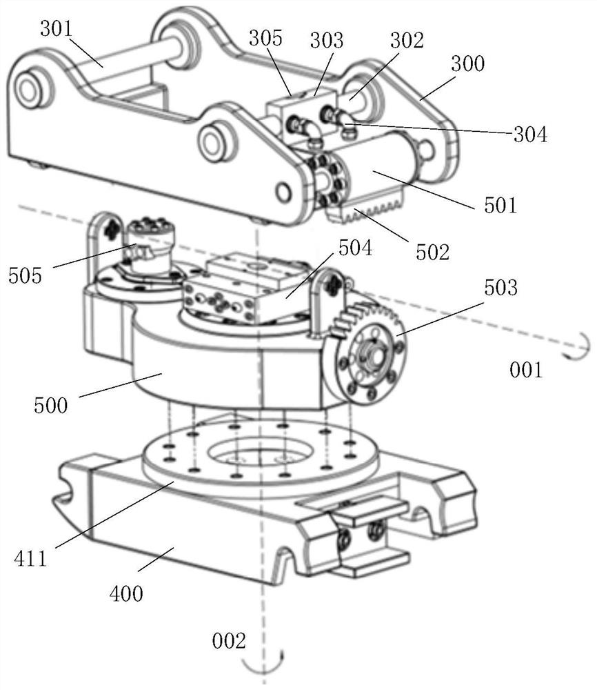
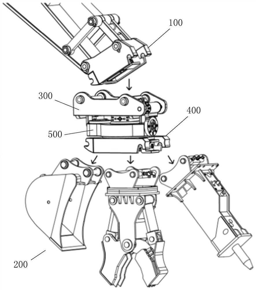
[0031] Such as Figure 1 to 2 As shown, the present embodiment provides a fully automatic fast displacement device for emergency rescue engineering equipment, which is suitable for the connection between the main strip 100 and the lower connection propagate 200 of the emergency rescue...


PUM


Abstract

The invention discloses a full-automatic quick-switching device for emergency rescue engineering equipment. An upper connecting device of the device is provided with a first front pin shaft and a first rear pin shaft which are connected with a first pin hook of a main machine bucket rod and a first locking butt joint mechanism. A lower connecting device of the device is provided with a second pin hook and a second locking butt joint mechanism which are connected with a second front pin shaft and a second rear pin shaft of a lower connecting accessory. A rectangular block is arranged in the middle of the rear pin shaft, and through holes for mounting female connectors are symmetrically formed in two ends of the rear pin shaft. A locking head is arranged at the telescopic end of each locking butt joint mechanism, a butt joint groove is formed in the middle of each locking butt joint mechanism, and through holes for installing male connectors are formed in the two ends of each butt joint groove. The pin hooks are connected with the front pin shaft and the rear pin shaft, and after the locking butt joint mechanisms lock the rear pin shaft, the female connectors in the rectangular block are in butt joint with the male connectors in the butt joint grooves. According to the technical scheme, the rescue requirements of quick switching and multi-degree-of-freedom operation of various machines and tools are met, and the problems that an existing quick switching device is complex in structure and high in manufacturing cost are solved.

Description

Technical field [0001] The present application covers the technical field of rescue equipment, in particular, involving a fully automatic fast displacement device for emergency rescue engineering equipment. Background technique [0002] For a long time, my country's technical research in high-end rescue equipment lags, existing rescue equipment function, poor motor, low automation, can not meet the construction rescue operation needs under complex terrain of earthquake, geological, etc., urgent needs to develop a small person or Unmanned, multi-function, intelligent rescue equipment. In particular, in response to the occurrence of multi-disaster-stricken disasters such as mountainous areas, it is necessary to quickly complete the disaster on-site composite disaster relief operation in a complex terrain environment, and realize the rapid switching of various machines such as mining, breaking and more freedom. Jobs to enhance disaster rescue and emergency treatment. [0003] In the...

Claims


Application Information

Patent Timeline
Patent Type & Authority Applications(China)
IPC IPC(8): E02F3/96E02F3/36E02F9/00
CPCE02F3/96E02F3/962E02F3/3631E02F3/3645E02F3/3663E02F9/006
Inventor 姜潮李伟张伟源陈启迪王靖杰
Owner HUNAN UNIV
Why Eureka
Try Eureka