

Household fan power supply detection equipment
A power supply detection and fan technology, which is used in power supply testing, components of electrical measuring instruments, and electrical measurement. Effect
- Summary
- Abstract
- Description
- Claims
- Application Information
AI Technical Summary
Problems solved by technology
Method used
Image

Examples
Embodiment 1
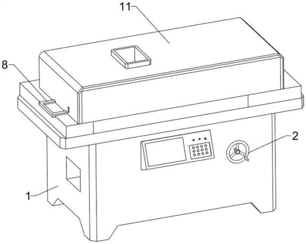
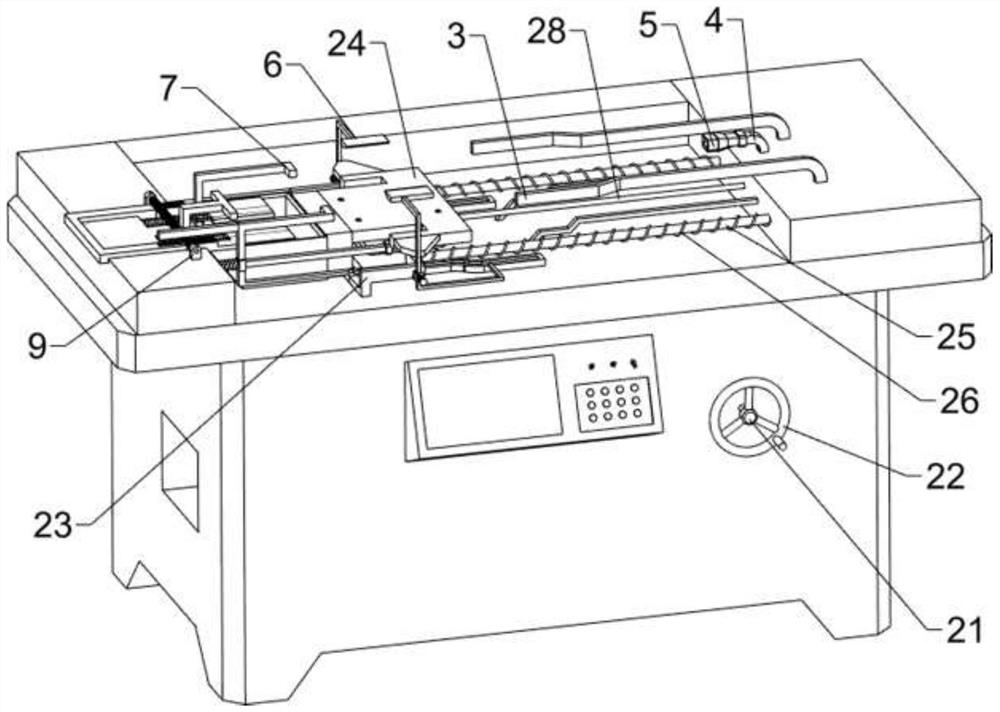
[0026] Such as Figure 1 ~ Figure 4 As shown, this embodiment discloses a household fan power detection device, which includes a detection table 1, a cover 11, a moving mechanism 2, a detection mechanism 3, a first fixed block 4, and a detection joint 5. The upper part of the detection table 1 is covered with a block Cover 11, a moving mechanism 2 is arranged on the upper part of the detection platform 1, a detection mechanism 3 is arranged between the right side of the upper part of the detection platform 1 and the moving mechanism 2, and a first fixed block 4 is connected in the middle of the upper right side of the detection platform 1, and the first fixed block 4. The left side of the upper part is connected with a detection joint 5.
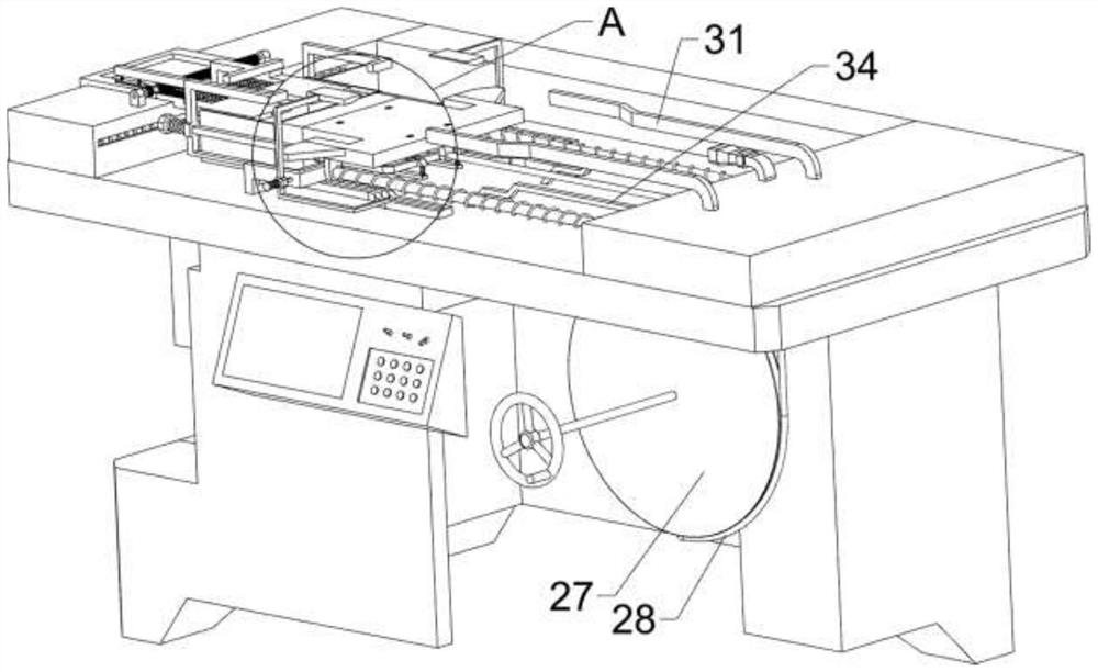
[0027] The moving mechanism 2 includes a first rotating shaft 21, a first turntable 22, a first fixed rod 23, a placement plate 24, a first guide rod 25, a first spring 26, a second turntable 27 and a stay cord 28. The first rotating shaft ...
Embodiment 2
[0031] Such as figure 1 , figure 2 , Figure 4 ~ Figure 7 As shown, in some embodiments, a snap assembly 6 is also included, and the snap assembly 6 includes a snap rod 61, a second guide rod 62, a third spring 63, a second baffle plate 64, a third guide rod 65, The fourth spring 66 and the first baffle plate 67, the outside of the right part of the first fixed rod 23 is connected with the second guide rod 62, and the second guide rod 62 is slidably connected with the clamping rod 61, and the clamping rod 61 and the placement plate 24 Cooperate with each other, the third spring 63 is connected between the clamping rod 61 and the guide rod, the first baffle plate 67 is connected to the upper left side of the clamping rod 61, and two third guide rods are connected symmetrically front and rear on the left side of the upper part of the detection platform 1 65, a second baffle 64 is slidably connected between the third guide rod 65, and two fourth springs 66 are connected symmet...
PUM
 Abstract
Description
Claims
Application Information