A material mixing machine suitable for viscous materials and a material mixing method for viscous materials

A technology of mixing machine and material, which is applied to mixing methods, mixers with rotary stirring devices, mixers, etc., can solve the problems of poor mixing effect and unsuitable viscous materials, etc., and achieve convenient material discharge and material mixing Uniform, easy-to-use results

Inactive Publication Date: 2017-06-20
HEBEI LIFU CHEM TECH
View PDF2 Cites 1 Cited by
  • Summary
  • Abstract
  • Description
  • Claims
  • Application Information

AI Technical Summary

Problems solved by technology

[0004] One of the purposes of the present invention is to provide a mixer suitable for viscous materials, so a

Method used


Image

  • A material mixing machine suitable for viscous materials and a material mixing method for viscous materials
  • A material mixing machine suitable for viscous materials and a material mixing method for viscous materials
  • A material mixing machine suitable for viscous materials and a material mixing method for viscous materials

Examples


Example Embodiment

[0036] Example 1: A mixer suitable for viscous materials.

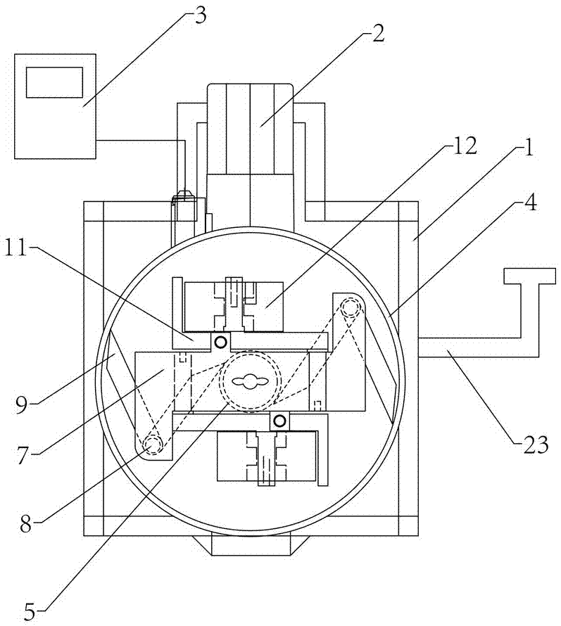
[0037] like figure 1 As shown, the present invention mainly includes parts such as frame 1, mixing device, motor 2 and control device 3.

[0038] Frame 1 comprises motor support and mixing tank support, and mixing tank support is arranged on the motor support, is provided with turning handle 23 on the motor support, after mixing finishes, pull turning handle 23, motor support, motor 2 , Mixing barrel 4 are turned over together to facilitate unloading.

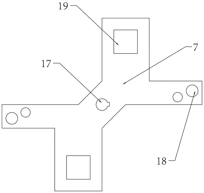
[0039] The mixing device includes a mixing tank 4 , a platform 7 arranged in the mixing tank 4 , and a scraper and a grinding wheel 12 arranged on the platform 7 .

[0040] The mixing tank 4 is a cylindrical barrel with an open top as the inlet of the material. For preventing the material in the tank from being polluted, a bung is provided on the top of the mixing tank 4 . A through hole is provided at the center of the barrel bottom plate of the mixing tank 4, and ...

Example Embodiment

[0053] Embodiment 2: the mixing method of viscous material.

[0054] The mixing method of viscous material comprises the following steps:

[0055] 1. The mixing machine mentioned in the embodiment 1 is set, the bung of the mixing tank 4 is opened, and the material to be mixed is added in the mixing tank 4.

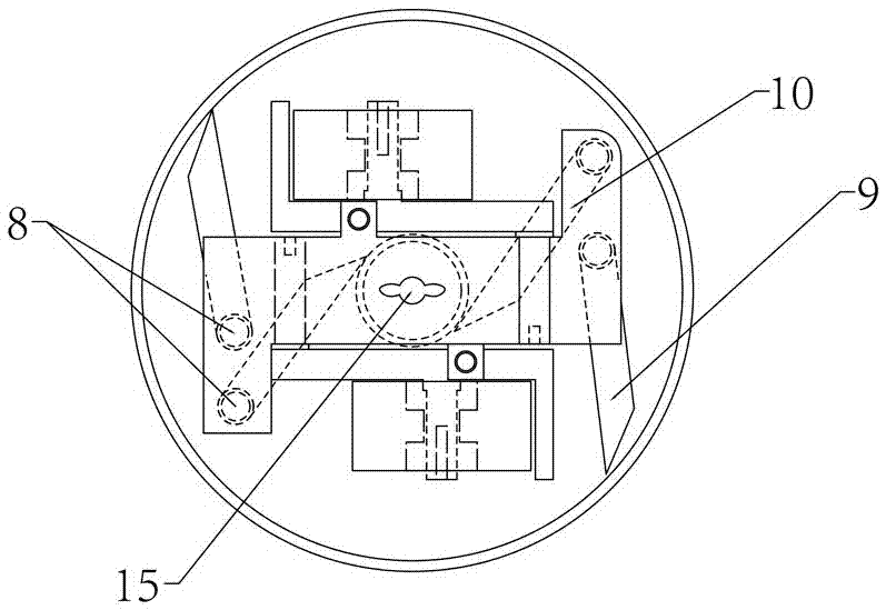
[0056] 2. Set the rotation speed and time according to the material characteristics, the control device 3 controls the motor 2 to start, the motor 2 rotates, and the platform shaft 6 drives the platform 7 to rotate, and the scraper and the roller 12 set on the platform 7 also rotate accordingly , during the rotation process, the grinding wheel 12 rolls the material in the barrel, so that the material adheres to the inner side wall of the mixing barrel 4 and the outer side wall of the core tube 5, and the outer scraper 9 will adhere to the inner side wall during the rotation process. The material on the inner wall of the mixing tank 4 is scraped off, and the inner scraper ...


PUM

PropertyMeasurementUnit
Viscosityaaaaaaaaaa
Viscosityaaaaaaaaaa

Abstract

The invention relates to a material mixing machine suitable for viscous materials and a material mixing method for viscous materials. The material mixing machine includes a rack, a material mixing device disposed on the rack and a motor disposed on the rack. The material mixing device includes a material mixing drum, a platform disposed in the material mixing drum, scraping plates disposed on the platform and runner wheels disposed on the platform. The material mixing drum is a cylindrical drum. A core tube is disposed in the material mixing drum. The tube axle of the core tube and the central axis of the material mixing drum coincide. A platform shaft penetrates through the core tube. The bottom of the platform shaft is in transmission connection with the motor after passing through the core tube. The platform is disposed at the top of the platform shaft. The lower platform surface of the platform is provided with scraping plate shafts. The scraping plates are disposed on the scraping plate shafts. The scraping plates include outer scraping plates the end edges of which are in contact with the side wall of the material mixing drum and inner scraping plates the end edges of which are in contact with the side wall of the core tube. A wheel support is disposed on the platform. The runner wheels are mounted the bottom end of the wheel support. The wheel support is provided with scraping sheets in contact with the circumference surface of the runner wheels. The material mixing machine and the method are suitable for materials with various sizes of viscosity, and can achieve uniform material mixing and no dead angle.

Description

technical field [0001] The invention relates to a mixing machine and a mixing method, in particular to a mixing machine suitable for viscous materials and a mixing method for viscous materials. Background technique [0002] In recent years, with the gradual popularization and mature application of the grinding process, the role of the mixing process in production has been rapidly raised to an important position. The performance of the mixing equipment not only directly affects the quality of the product, but also affects whether the production can continue normally, which in turn affects the economic benefits of the enterprise. [0003] Existing mixers usually shake the mixing barrel so that the material particles in the barrel move with the barrel and contact each other, thereby achieving the purpose of mixing. However, for materials with slightly higher viscosity, the above mixer is not suitable. Because during the shaking process of the mixing tank, the slightly viscous...

Claims


Application Information

Patent Timeline
IPC IPC(8): B01F7/02B01F15/00B01F3/10B01F23/47
CPCB01F23/47B01F27/171B01F27/60B01F35/123
Inventor 杨志平刘学千芦永佳娄双双崔大龙赵金鑫
Owner HEBEI LIFU CHEM TECH
Why Eureka
Try Eureka