Multifunctional feed stirring device

A feed mixing and multi-functional technology, which is applied to feed, mixer accessories, mixers with rotary mixing device, etc. Effect

Inactive Publication Date: 2018-01-09
重庆新动生物技术有限公司
View PDF1 Cites 2 Cited by
  • Summary
  • Abstract
  • Description
  • Claims
  • Application Information

AI Technical Summary

Problems solved by technology

[0004] In view of the above problems, the present invention provides a multi-functional feed mixing equipment, which solves the problems of inconveni

Method used


Image

  • Multifunctional feed stirring device
  • Multifunctional feed stirring device

Examples


Embodiment 1

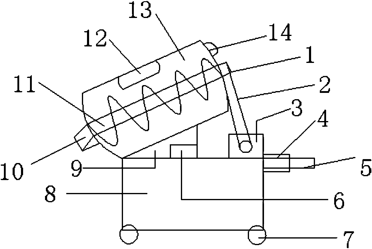
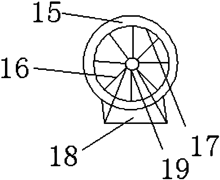
[0013] refer to figure 1 , figure 2 , a multifunctional feed mixing equipment, its structure includes a driven wheel device 1, a belt 2, a motor 3, a handle 4, a non-slip handle 5, a display 6, a wheel device 7, a power distribution box 8, a gravity sensing inclined block 9, an outlet Material port 10, spiral stirring rod 11, feed port 12, mixing barrel 13, exhaust port 14, the driven wheel device 1 is connected with the motor 3 through the belt 2, and the display 6 is located on the side of the gravity sensing inclined block 9 , the display 6 is connected to the gravity sensing slanting block 9 through a circuit, the gravity sensing slanting block 9 is fixedly connected to the distribution box 8 through a nut, and the inclined surface of the gravity sensing slanting block 9 is connected to the mixing tank 13 Connected by welding, the discharge port 10 is located at the tail of the mixing tank 13 and connected by welding, the upper end of the spiral stirring rod 11 is connec...


PUM


Abstract

The invention discloses a multifunctional feed mixing equipment, which comprises a driven wheel device, a belt, a motor, a handle, an anti-slip handle, a display, a wheel device, a power distribution box, a gravity sensor inclined block, a discharge port, and a spiral stirring rod , feed inlet, mixing barrel, exhaust port, the inclined plane of the gravity sensing inclined block is connected with the mixing barrel by welding, the outlet is located at the tail of the mixing barrel and connected by welding, the upper end of the spiral stirring rod is connected with the mixing barrel from The driving wheel device is connected, the lower end is connected with the discharge port, the feed port is located on the side wall of the mixing tank, and the exhaust hole is located at the top of the mixing tank, close to the driven wheel device. The wheel of the present invention has fixed feet, which is more stable when used, and has a gravity sensing inclined block, which is convenient for weighing during stirring. It is equipped with a power distribution box, which is more convenient to use.

Description

technical field [0001] The invention relates to the field of mixers, in particular to a multifunctional feed mixing device. Background technique [0002] Feed pulverizers are divided into self-priming feed pulverizers and forced-feed pulverizers, and feed mixers are divided into vertical feed mixers and horizontal feed mixers. Commonly used mixer models are 500 and 1000, and the mixing volume of each batch is 500 kg and 1000 kg. [0003] The prior art discloses a feed mixer with an application number of 201320465458.5. The feed mixer includes a mixing drum, and a stirring shaft is arranged in the mixing drum. Its main feature is that the mixing drum is arranged on a support shaft through a large bearing. Both sides of the mixing drum are equipped with end covers of the mixing drum; the stirring shaft is driven by the motor Ⅰ through the transmission belt Ⅰ, and the stirring shaft is set on the support shaft through a small bearing; The shaft is fixedly connected, driven by...

Claims


Application Information

Patent Timeline
IPC IPC(8): B01F7/08B01F15/00A23N17/00
Inventor 何洪政
Owner 重庆新动生物技术有限公司
Why Eureka
Try Eureka