Connecting structure of split type toner bin

A connection structure, split technology, applied in the electric recording process applying charge pattern, the equipment of electric recording process applying charge pattern, electric recording technique, etc., can solve the problem of powder leakage, contamination of printed images, and high replacement cost, Achieve the effect of avoiding toner spillage, ensuring print quality, and low toner filling requirements

Pending Publication Date: 2021-07-23
NINGBO DELI KEBEI TECH CO LTD
View PDF0 Cites 0 Cited by
  • Summary
  • Abstract
  • Description
  • Claims
  • Application Information

AI Technical Summary

Problems solved by technology

Due to the many internal components of the toner cartridge, the replacement cost is high, and if the user fills the toner cartridge by himself, it is easy to cause powder jams or leakage during printing due to improper operation, which will affect the printing effect or pollute the printed image
However, in the existing split-type toner cartridge structure, the powder bin and the developing roller are usually separated into one component. When the toner in the toner bin is used up, the powder bin and the developing roller need to be replaced at the same time, and the replacement cost is relatively high, and Usually, the toner bin and developing roller are arranged in the printer casing. When replacing the toner bin, you need to open the cover at the corresponding position on the printer, which is inconvenient to operate. You need to open the printer cover and then take out the toner bin.

Method used


Image

  • Connecting structure of split type toner bin
  • Connecting structure of split type toner bin
  • Connecting structure of split type toner bin

Examples


Embodiment Construction

[0025] The present invention will be further described in detail below in conjunction with the accompanying drawings and embodiments.

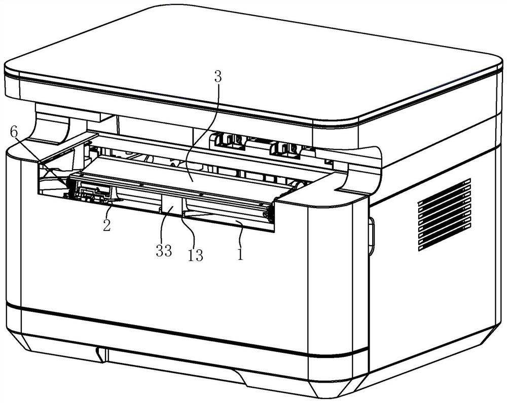
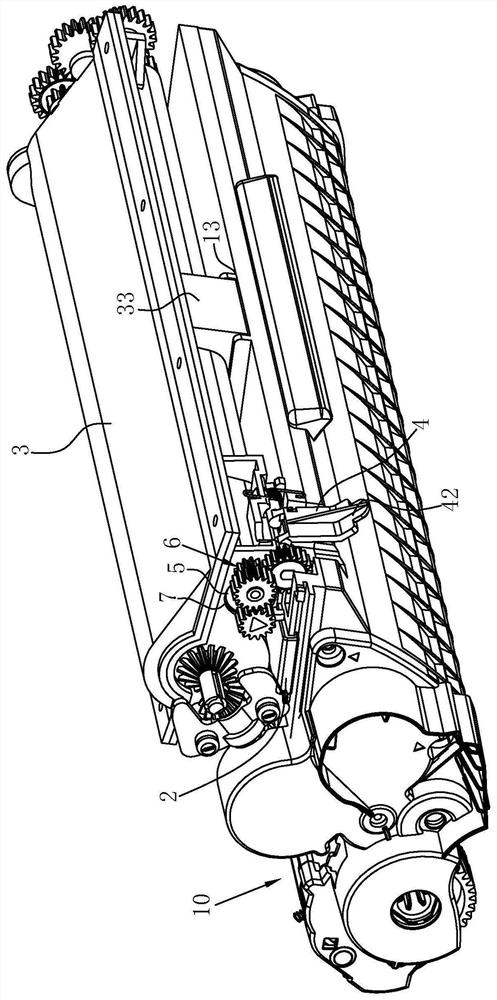
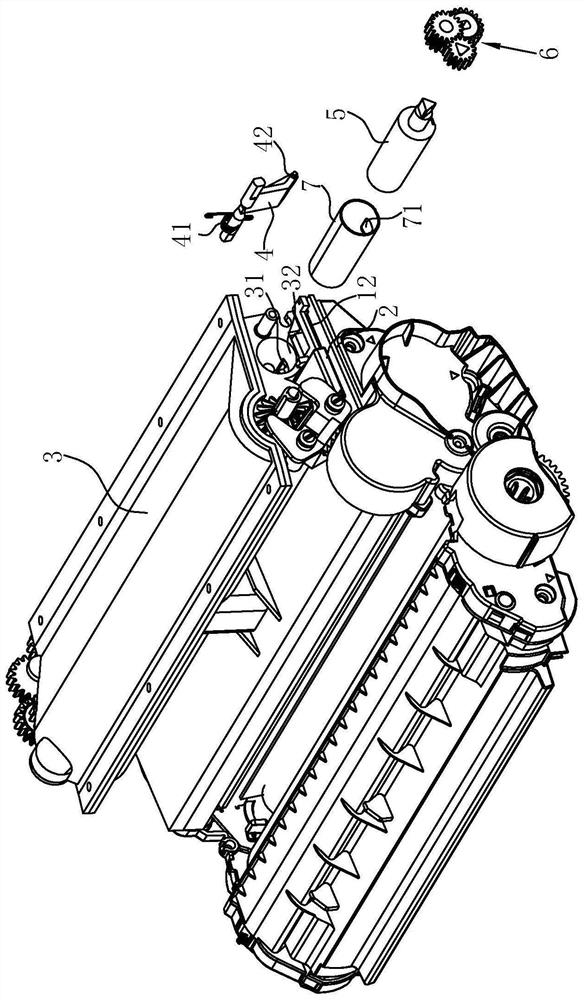
[0026] Such as Figure 1 to Figure 4 As shown, the connection structure of the split toner bin in this embodiment includes a toner bin 1 , a first cover 2 , a toner bin box 3 , a second cover 4 , a powder outlet 5 , and a transmission mechanism 6 .

[0027] Wherein the toner cartridge 1 is integrally connected to the toner cartridge body 10, and the toner cartridge body 10 is a toner cartridge assembly in the prior art, including components such as a photosensitive drum, a developing roller, a transfer roller, a charging roller, and the toner cartridge 1 communicates with the developing roller. , the toner in the toner chamber 1 can be evenly distributed on the developing roller under the action of the scraper. The toner bin 1 is provided with a toner inlet 11 , and the toner in the toner bin box 3 can enter into the toner bin 1 through the t...


PUM


Abstract

The invention relates to a connecting structure of a split-type toner bin. The connecting structure comprises the toner bin integrally connected to a toner cartridge main body and provided with a toner inlet; a first cover body which is movably connected to the toner bin and can open and close the toner inlet; a toner bin box which can be matched with the toner bin in a relatively movable manner, wherein a toner outlet matched with the toner inlet is formed in the toner bin box; a second cover body which is movably connected to the toner bin box and can open and close the toner outlet; a toner outlet piece, wherein the position, corresponding to the toner outlet, of the toner outlet piece is movably arranged in the powder bin box, and a first opening matched with the powder outlet is formed in the powder outlet piece; and a transmission mechanism in transmission connection between the second cover body and the powder outlet piece, wherein the transmission mechanism can drive the first opening of the powder outlet piece to move towards the powder outlet along with the opening action of the second cover body. According to the connecting structure of the split type toner bin, the toner bin box is arranged independent of the toner bin, so that a user can conveniently fill the toner or reduce the replacement cost of the toner bin by himself / herself, and the situation that the toner is scattered in the assembling process is avoided.

Description

technical field [0001] The invention relates to the technical field of laser printers, in particular to a connection structure of a split powder bin. Background technique [0002] The toner cartridge mechanism used in the existing laser printer is mainly divided into an integrated toner cartridge structure and a split toner cartridge structure. The one-piece toner cartridge structure integrates the imaging unit and the developing unit in the toner cartridge, and the user needs to replace the whole toner cartridge or refill it by himself after using up the toner in the toner cartridge. Due to the many internal components of the toner cartridge, the replacement cost is high, and if the user fills the toner cartridge by himself, it is easy to cause powder jam or leakage during printing due to improper operation, which will affect the printing effect or pollute the printed image. However, in the existing split-type toner cartridge structure, the powder bin and the developing ro...

Claims


Application Information

Patent Timeline
IPC IPC(8): G03G15/08
CPCG03G15/0865G03G15/0886
Inventor 王立成徐鑫炎李一王奇
Owner NINGBO DELI KEBEI TECH CO LTD
Why Eureka
Try Eureka